ments or heaters). With a cold cathode, sufficient
electron emission is available to form a space charge
when an electric field is applied. The electrons will
not achieve sufficient velocity to escape the region
close to the cathode without an RF field applied.
Initially, when an RF field is applied, the electrons
gain some energy from the RF and move farther out
from the cathode. While some will gain even more
energy and reach the anode, others will return to the
cathode and strike with sufficient energy to cause
secondary emission and increase the electrons in the
space charge. Therefore, the major source of electrons
is secondary emission from the reentrant electrons.
Secondary emission generates heat in the cathode
and further increases emission. If the cathode be-
comes too hot, thermionic emission may become
sufficient to allow the tube to oscillate or to produce
noise, even though an RF field has not been applied.
To prevent the spurious generation of noise, the
cathode is usually water-cooled. Another means of
reducing noise output is to make the RF pulse slightly
wider than the high-voltage pulse.
Further control is found on some tubes with a bias
electrode (a cutoff electrode). The bias electrode has
a positive pulse (with respect to the cathode) applied
just before the end of the RF pulse. The cutoff pulse
allows the electrode to collect the electrons in the
drift-tube region and the tube to shut off. The pulse
must be wide enough to extend past the end of the RF
pulse.
CFAs do not have the gain of some of the linear-
beam tubes. However, they do have three advantages.
1. The CFAs, when used in a multistage chain,
can produce equal or greater overall gain at lower
high-voltage requirements than a linear- beam ampli-
fier, such as a multicavity klystron. For example, a
typical CFA can deliver a 1-megawatt RF peak power
output with a 40-kilovolt, 50-ampere peak pulse,
where a klystron would require a 90-kilovolt, 40-am-
pere peak pulse to produce the same RF output.
However, the CFA would require a higher power level
input drive signal than the klystron.
2-12
2. The CFA is a cold cathode, which normally
has a much longer operating life than a heated cath-
ode.
3. The CFA produces far less X-rays than linear-
beam tubes; therefore, lead shielding is not required.
LINEAR-BEAM TUBES
A linear-beam tube uses a magnetic field that is
parallel to the electron beam and is used to focus the
beam. Some tubes do not use a magnetic field; in-
stead, electrostatic focusing is used to hold the beam
together while it travels the length of the tube. The
two most common types of linear-beam tubes used in
fire-control equipment are the klystron amplifier and
the traveling-wave tube.
Klystron Amplifiers
The basic theory of a klystron amplifier is quite
simple. The klystron amplification principle may be
readily explained with an analogy to a simple triode
amplifier with tuned plate and grid circuits. Klystron
amplifiers include two-cavity power klystrons and
multicavity power klystrons.
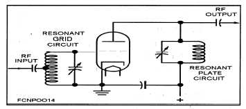
TWO-CAVITY POWER KLYSTRON AM-
PLIFIERS.— Figure 2-8 shows a simplified sche-
matic of a triode amplifier with resonant circuits at
both the input and the output. Such resonant circuits
restrict the bandwidth of the amplifier and increase
the gain.
Figure 2-8.—Simplified schematic of a triode amplifier
with resonant circuits at both the input and the output.