The operating frequency of a TWT oscillator is
determined by the pitch of the tube’s helix. The os-
cillator can be tuned, within limits, by adjusting the
operating potentials of the tube.
The electron beam passing through the helix in-
duces an electromagnetic field in the helix. Although
initially weak, this field will cause bunching of suc-
ceeding portions of the electron beam.
With the proper potentials applied, the bunches of
electrons reinforce the signal on the helix. This, in
turn, increases the bunching of succeeding portions of
the electron beam. The signal on the helix is sustained
and amplified by this positive feedback, resulting
from the exchange of energy between the electron
beam and the helix.
MODULATORS
Transmitter tubes all have one common require-
ment—a source of high voltage—whether they are
operated in a CW or pulsed mode. A fixed high-
voltage supply for CW operation is relatively simple
compared to a pulsed high-voltage supply. A pulsed
high-voltage power supply is called a modulator,
which means to shape, as well as to control. Modu-
lators are also called pulsers or keyers, depending on
their circuit function.
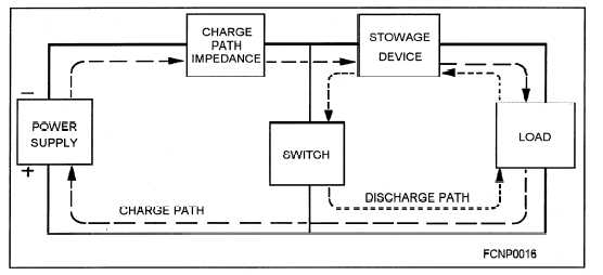
The power supply provides the source of high
voltage to charge the storage device. The storage de-
vice can be capacitive or inductive, or a combination
of capacitance and inductance that stores electrical
energy in the form of an electrostatic or electro-
magnetic field. Electrostatic storage is the most com-
mon method used.
The storage device is charged through the rela-
tively high impedance of the charge path while the
switch is open. The load is the high-power tube,
which is usually connected by a step-up pulse trans-
former. The pulse transformer allows the dc to charge
the storage device.
When the switch is closed, a low-impedance dis-
charge path is provided for the storage device through
the pulse transformer. The charge time is long com-
pared to the discharge time because of the differences
in impedances. The switch is normally an electronic
element, such as a thyratron or a silicon-controlled
rectifier (SCR), since mechanical switching is im-
practical at the pulse-repetition frequencies used in
most radars.
There are many different types of pulse modula-
tors in use today. The most common type found in
fire-control applications is the line modulator. The
basic elements of a line modulator are shown in figure
2-10.
Figure 2-10.—Basic elements of a modulator.
2-20