Nutation
The nutation process is difficult to describe in
words, but easy to demonstrate. Hold a pencil with
both hands, one hand at the eraser end and the other
hand at the point. While holding the eraser end as still
as possible, move the point in a circle to form a cone.
The motion of the pencil is called nutation. The pencil
point corresponds to the transmitting end of a wave-
guide feed.
The important point is that the polarization of the
RF beam does not change during a nutation cycle.
This means that the axis of the moving feed horn must
not change horizontal or vertical orientation while the
feed is moving. The movement might be compared to
that of a Ferris wheel; the orientation of the seats re-
mains vertical, regardless of where they are on the
wheel.
Nutating Waveguide
The waveguide feed is a metal pipe, usually rec-
tangular in cross section. The open end of the wave-
guide feed faces the antenna disk reflector, and the
energy it emits is bounced from the reflector surface.
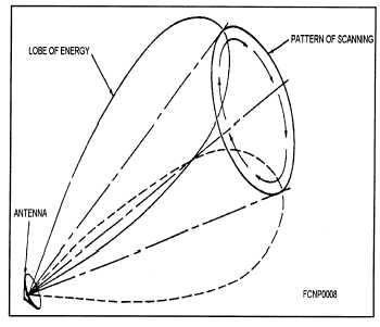
A conical scan can be generated by nutation of the
waveguide feed. In this process, the axis of the
waveguide feed is nutated through a narrow conical
pattern.
This movement is fast (from 30 to 60 hertz) and
small in amplitude. To an observer, the waveguide
feed would appear to be vibrating slightly. The ampli-
tude of the nutation determines the angle of the cone.
The amplitude is kept small so that sufficient power
is present in the center of the conical pattern for target
tracking. Figure 2-5 shows the conical pattern pro-
duced by nutating the RF beam.
Angle Tracking
The radar’s angle error-detecting circuits provide
correction signals to the antenna and director drive
circuits. The correction signals are proportional to the
Figure 2-5.—Nutating lobe.
target displacement from the nutation axis of the an-
tenna. Target displacement is detected by first locking
onto the target in range, so that only that target is
gated and used for angle tracking.
A two-phase reference generator in the antenna
establishes the position of the feed horn relative to the
nutation axis of the antenna. The generator provides
the reference voltages for the angle error-detection
circuits. The elevation reference voltage is 900 out of
phase with the azimuth reference voltage.
Each error-detector circuit compares the phase of
its reference voltage with the phase of its video en-
velope. The phase comparison indicates the direction
of the error. The amplitude modulation of the video
envelope is compared to the amplitude of the refer-
ence voltage to determine the amount of error.
ELECTRONIC SCANNING
Several techniques are used for electronic scan-
ning. The two most common techniques used in fire-
control radars are monopulse (simultaneous lobing)
scanning and phasing scanning.
Monopulse scanning does not move the trans-
mitted beam; instead, the echo signal is scanned or
2-6