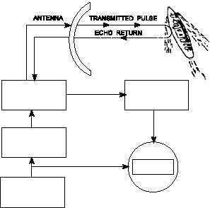
Synchronizer
The heart of the radar system is the synchronizer. It
generates all the necessary timing pulses (triggers) that
start the transmitter, indicator sweep circuits, and
ranging circuits. The synchronizer may be classified
as either self-synchronized or externally synchro-
nized.
In a self-synchronized system, pulses are
generated within the transmitter.
Externally
synchronized system pulses are generated by some
type of master oscillator external to the transmitter,
such as a modulator or a thyratron.
Transmitter
The transmitter generates powerful pulses of
electromagnetic energy at precise intervals. It creates
the power required for each pulse by using a
high-power microwave oscillator (such as a mag-
netron) or a microwave amplifier (such as a klystron)
supplied by a low power RF source.
For further information on the construction and
operation of microwave components, review NEETS
Module 11,
Microwave Principles, NAVEDTRA
172-11-00-87.
Duplexer
The duplexer is basically an electronic switch that
permits a radar system to use a single antenna to
transmit and receive. The duplexer disconnects the
antenna from the receiver and connects it to the
transmitter for the duration of the transmitted pulse.
The switching time is called receiver recovery time,
and must be very fast if close-in targets are to be
detected.
Receiver
The receiver accepts the weak RF echoes from the
antenna system and routes amplified pulses to the
display as discernible video signals. Because the radar
frequencies are very high and difficult to amplify, a
superheterodyne receiver is used to convert the echoes
to a lower frequency, called the intermediate frequency
(IF), which is easier to amplify.
Displays
Most of the radars that FCs operate and maintain
have a display, or multiple displays, to provide the
operator with information about the area the radar is
searching or the target, or targets, being tracked. The
usual display is a cathode-ray tube (CRT) that provides
a combination of range, bearing (azimuth), and (in
some cases) elevation data. Some displays provide raw
data in the form of the signal from the radar receiver,
while others provide processed information in the form
of symbology and alphanumerics.
Figure 1-5 shows four basic types of displays.
There are other variations, but these are the major types
encountered in fire control and 3-D search radars.
TYPE A.—The type A sweep, or range sweep,
display shows targets as pulses, with the distance from
the left side of the trace representing range. Variations
in target amplitude cause corresponding changes in the
displayed pulse amplitude. The display may be bipolar
video when used with Moving Target Indicator (MTI)
or pulse Doppler radars.
TYPE B.—The type B sweep, or bearing sweep, is
mostly found with gunfire control radars and is used
with surface gunfire to spot the fall of shot. The range
may be full range or an interval either side of the range
gate.
TYPE E.—Two variations of type E are shown.
Both provide range and elevation or height of a target.
These are associated with height-finding radars and are
1-6
DUPLEXER
RECEIVER
SYNCHRONIZER
TRANSMITTER
DISPLAY
SUPPORT
SYSTEMS
COOLING
AIR
POWER
CONTROL
GROUP
Figure 1-4.—Basic radar block diagram.