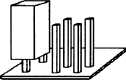
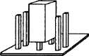
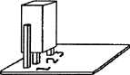
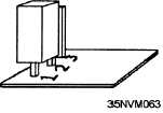
Figure 8-19.—Jumper connections.
switches except that you must physically remove and
reinsert them. A jumper connector is designed for easy
removal and reinsertion. They are permanent unless a
configuration change is required. The jumper
connector consists of a receptacle and plug
arrangement. The receptacle is normally mounted
permanently on the pcb’s and/or backplane/
motherboard inside the micro’s chassis. A plug (with
or without a cable) makes the appropriate connection.
It disables, enables, selects, and expands. Jumpers
define the configuration of each pcb, which will
eventually affect operations. Some of the functions
affected include mode of operation (fast or normal),
clock speed, wait states, and I/O connections. Like DIP
switches, jumpers are designed so you can manually
position them during component installation, removal,
or initial system configuration to inform the processor
of the availability of the particular components, as well
as the requirements of the system operators. Individual
jumpers or combinations of two or three jumpers are
used to specify a variety of configuration options.
Battery Protected Storage. —Many newer
microcomputers have a hardware setup/configuration
program stored as firmware. It has the capability to
display system configuration data on the display screen
and to update system configuration data via the
keyboard. The configuration data is stored in a random
access memory (RAM) protected by a rechargeable
battery so the data is retained for long time periods when
the micro itself is powered down. The battery is located
on the backplane/motherboard.
Configuration Options. —Both DIP switches and
battery protected storage provide the same basic
configuration data to the micro.
System setup/
configuration options include the following:
Date/time data (battery protected storage only)
Base and expansion memory size
Floppy disk drive identifiers (A, B, C or O, 1,2)
Storage capabilities (number of Kbytes of
storage per drive)
Hard drive data
Boot drive identifier
Type of video display
Video refresh time period
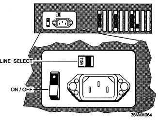
APPLY POWER. —Power is applied to the
microcomputer with a simple ON/OFF switch usually
mounted on the back of the desktop computer chassis
(fig. 8-20). A separate monitor requires its own power
switch. Portable micros usually have fixed time period
rechargeable batteries (6, 8, or 12 hours) with a normal
ac power option. Presence of system power is indicated
by single indicator lamps on the front of the chassis and
the monitor mounting. Sometimes in the same area as
the ON/OFF switch, a selectable switch (fig. 8-20)
called a voltage or line select switch allows the
microcomputer to operate on voltages in the range of
100 to 130 volts or 200 to 230 volts.
USE CONTROLS, DATA ENTRY, AND
DATA DISPLAY. —Micros, either portable or desktop
Figure 8-20.—Desktop computer back panel.
8-17