Figure 4-17.—Example of command enable used in a circuit.
Adders and subtracter circuits can be serial or parallel.
See figure 4-16 for an example of a full-adder circuit.
Command signals (enables) —These circuits
provide the enable to route information from one
destination to another, such as transferring the contents
of one register to another. Other examples are to set a
condition, start a timing chain, or select an address. See
figure 4-17. A closer look indicates that the only time
a set side of the B register will be a 1 is when a set side
of the A register is set and the A register
B register
command is enabled (H).
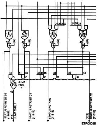
Comparator —Comparator circuits can be used
to compare incoming binary numbers after
mathematical operations have been performed on them;
for example, to check if two numbers are equal and so
on. They can also perform any of several logic gating
operations on bits of two binary bits coming in, such as
AND and OR operations. In addition, they perform a
wider range of comparison operations, such as
less-than-or-not and equals-or-not, and these
comparisons can be applied to individual bits of two
input numbers. Figure 4-18 is an example of a
comparator circuit (an arithmetic detection cir-
cuit).
Figure 4-18.—Example of a comparator circuit (an
arithmetic detection circuit).
4-13


