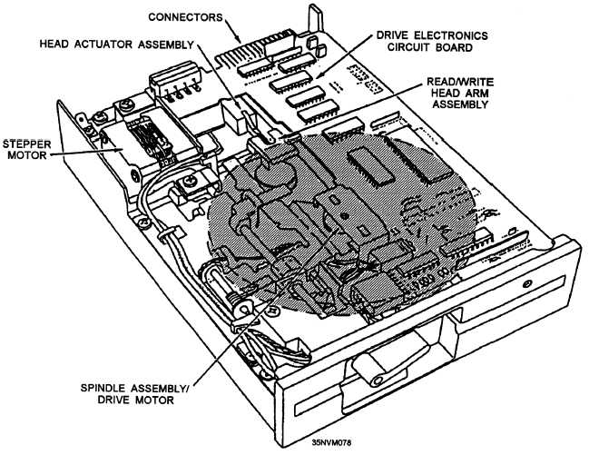
Figure 10-7.—A typical floppy disk drive.
Drive Electronics Circuit Board
Mounted to the disk drive is the drive electronics
circuit board. This board contains the circuitry that (1)
controls the electromechanical parts of the disk drive,
(2) controls the operation of the read/write heads, and
(3) interfaces the floppy disk drive to the disk controller
in the computer.
Connectors
On the back of the drive electronics circuit board
are at least two connectors. The 4-pin, in-line connector
supplies power to the drive. The 34-pin edge connector
provides control signals to the drive and exchanges data
between the drive and the disk controller in the
computer.
Head Actuator
The head actuator assembly is a mechanical motor
assembly that actually moves the heads over the disk.
It does this by using a stepper motor. This motor moves
in very small fixed increments or steps. Each increment
of the stepper motor defines one track; therefore, if we
want to read data on track 20, and the heads are at track
10, the stepper motor must be incremented 10 times to
reach track 20.
Read/Write Head Assembly
Floppy disk drives have two read/write head
assemblies, one for each side of the floppy disk. The
heads are mounted on arms that connect to the head
actuator assembly. Since the heads are mounted to a
single head actuator, they move in unison with each
other.
10-9