Figure 8-6.—Illustration of instruction word format IV-A.
word. First the computer executes the upper half-word
instruction then the lower. If only one of these format
instructions is to be stored in a memory word, then it is
stored in the upper half-word location. An active status
register (ASR) bit (215) is used to keep track of
upper/lower half instruction execution.
Format IV-A instructions are used for a variety of
computer operations that do not require an operand or
operand address to be part of the instruction. These
operations include but are not limited to mathematics
and comparison operations, IOC commands, task and
executive state operations, and real-time or monitor
clock operations.
The format IV-A instruction (fig.
8-6) is made up of an f field, a field, f4 field, an index
designator (b) field, and i field, which is unused unless
specified. The only field we have not covered is the f4
field, a 3-bit subfunction code. This field can be used
to identify code memory registers (CMR) for CMR
operations.
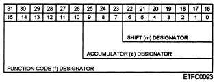
Format IV-B instructions are used to shift data
stored in an accumulator. The accumulator designator
specifies an accumulator in control memory. The shift
count designator specifies a shift count or a source of a
shift count. Instruction format IV-B (fig. 8-7) is made
up of an f field, an a field, and a shift designator (m)
field.
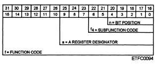
Format IV-C —Format IV-C instructions (fig.
8-8) are used for individual bit operations. These
operations include setting, clearing, or testing an
individual bit of a specified accumulator register. The
5-bit n field provides the bit position pointer to specify
the register bit to be operated on.
Format V —Format V instructions are full-word
format instructions (fig. 8-9) used for single and
double-precision floating-point math operations and
other large magnitude number functions. In this format
the f, f5, and f6 fields are used to define the specific
operation to take place. The a and b fields are used for
accumulator and index register definition. The m field
provides decimal point positioning values for floating
point operations.
INSTRUCTION OPERAND ADDRESSING
The types of operand addressing usually available
are direct, extended, immediate, implicit, indexed,
indirect, and relative.
Direct Operand Addressing
In direct operand addressing, the address of the
operand’s memory location is contained in the
instruction. Figure 8-10 shows an example of direct
addressing format.
Figure 8-7.—Illustration of instruction word format IV-B.
8-10
Figure 8-8.—Il1ustration of instruction word format IV-C.