Subassembly or pcb mounting slides and
retaining hardware
Subassembly or pcb electrical connector
receptacles and interconnecting wiring harness
Printed circuit boards
External connections for data and power cables
An operator’s control or maintenance panel
Power supply unit
Blower unit
Air falter
In a cage or rack arrangement, only the functional
areas of the computer are contained in the cage or rack.
The cage or rack contains pcb’s that only house the
major functional areas, such as CPU, memory, and I/O.
Sometimes more than one functional area will be
contained on a pcb. The pcb’s slide into slots inside the
cage or rack.
The connector receptacles for each
subassembly or pcb are usually located at the rear of the
cage or rack. The pcb’s are not always keyed, so you
must exercise care when installing them. The pcb’s are
secured in each slot by retaining hardware. The cage or
rack is generally fixed and cannot be extended as a
whole unit. The pcb’s can usually be accessed with
power on, but power must be secured when you remove
and replace a pcb.
The pcb’s can be extended
individually for rnaintenance.
The other main parts of the computer, such as the
power supply unit and cooling unit, are located in a
different part of the frame or cabinet, not in the cage or
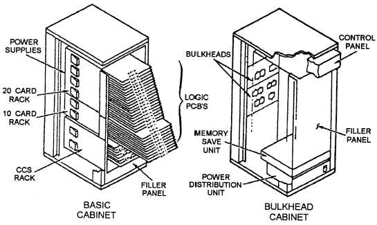
rack with the pcb’s. Figure 2-12 is an illustration of a
cage or rack setup.
Motherboard- or Backplane-Designed
Computer Framed/Cabinets
Computers that use a motherboard or backplane
design are built more for their portability and
compactness. They are the least rugged. The frame or
cabinet contains the following:
A motherboard or backplane with the connector
receptacles for each pcb, the keyboard, and in
some types of micros: single inline memory
modules (SIMMs), single inline packages
(SIPS), and single inline pin packages (SIPPs)
Wiring harness for the motherboard or
backplane
Pcb’s with the necessary I/O connectors
External connections for the power cables
Retaining hardware for the motherboard or
backplane
A power supply unit
A small fan with an air filter for cooling
A small speaker
Figure 2-12.—Example of a cage- or rack-designed computer frame or cabinet
2-11