FLOW REGULATORS
Many different types and sizes of flow-regulating
devices are used in both the primary and secondary
cooling systems to reduce the pressure or flow of
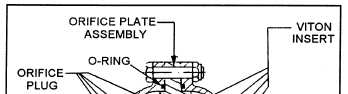
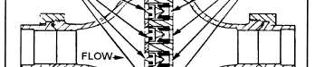
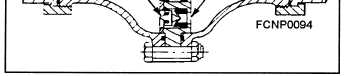
coolant through a cooling system. Figure 2-12 shows
a constant-flow regulator.
Figure 2-12.—Constant-flow regulator.
The orifice plate is found primarily in the seawater
cooling system. It is the simplest design of a flow-
regulating device and consists of a steel plate with a
hole in it. With constant known seawater pressure and
with a given hole size, the volume of water through
the device can be determined. The use of an orifice
plate is limited to where the input water pressure is
essentially constant, such as the ship’s fire main.
The orifice plate is normally installed between
two pieces of flanged pipes upstream from the heat
exchanger. This reduces the ship’s fire-main pressure
below the pressure in the secondary cooling system.
If one of the heat exchanger tubes fails, the seawater
pressure will be lower than the distilled-water pres-
sure; therefore, it will not contaminate the secondary
cooling system, as the secondary cooling system will
force distilled water into the primary cooling system.
A ruptured heat exchanger tube or a bad single-
tube sheet in a heat exchanger will give no visual indi-
cation of water loss except for the indication on the
expansion tank sight glass.
To stabilize the flow of seawater and to prevent jet
erosion of the heat exchanger and associated piping,
the orifice plate should be installed with at least 15
pipe diameters of straight pipe upstream from the heat
exchanger. When there is a drop in the heat exchanger
primary input pressure and the seawater supply pres-
sure has not changed, you should first check the du-
plex strainer differential pressure gage to ensure that
the duplex strainer is clean. Then you should inspect
the orifice plate for deposits or particles that could
restrict the seawater flow. Also, you should inspect
the orifice plate for erosion damage of the hole diam-
eter. (Replace the orifice plate when there is an in-
creased flow of seawater to the point that it could
damage the heat exchanger.)
Never use the seawater valves to throttle (partially
close) the flow of seawater in the primary cooling sys-
tem, because the seawater will erode the internal parts
of the valve. Such misuse would damage the valve, re-
quiring extensive repair or replacement because it
would no longer close properly.
When used with the chilled-water system, the
constant-flow regulator (variable orifice) is installed
downstream from the heat exchanger. This restricts
the flow from the heat exchanger and keeps the heat
exchanger fully submerged for greater efficiency (heat
transfer). This flow regulator is not used in the sea-
water system because the internal parts would easily
become fouled with marine growth and deposits. The
operation is dependent on the movement of the orifice
plugs (neoprene) to regulate the flow of water.
The equipment-flow regulator is used primarily
with electronic equipment to regulate the flow of dis-
tilled water through the individual cabinets and
components. It maintains a constant flow of distilled
water with limited changes in the input pressure. At
the minimum water flow, the total amount of water is
passed through the device. As the flow of water in-
creases to the flow regulator’s maximum limit, the
water flow is restricted by the movement of the insert,
which causes the hole size to decrease, thereby regu-
lating the flow of water. The amount of water that the
flow regulator will pass is usually stamped on the side
of the regulator. This is because the external dimen-
2-15