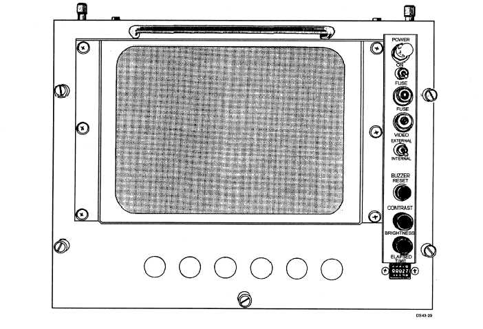
Figure 3-23.—Digita1 display indicator.
changes. It then transmits the input words to the CDS
computer in response to interrogations.
ANALOG AREA.— The analog area receives DC
and DU pulse trains, range marks, end-of-sweep, and
video from the RDDS. This data is used to generate
the sensor sweep and video display. The digital area
of a CIGARS-equipped console provides the symbol
control signals (SIGN X, X, 2X, SIGN Y, Y, 2Y, Z,
and W) and offset data for sweep and symbology. In
systems that use a symbol generator, symbol
waveforms and unblinking signals are inputted
directly into the analog section.
Digital Display Indicator (DDI)
The IP-1304/UYA-4(V) digital display indicator
(DDI) shown in figure 3-23 is also called digital data
indicator.
It is a raster scan formatted video
monitor. It accepts computer-generated alphanumeric
(ASCII) and line display data, stores the data in an
internal refresh (video) memory, and converts the
stored data into monochrome raster scan video
signals.
The DDI is capable of displaying sixteen 64-
character lines (1,024 characters) in the internal video
mode. The DDI is also designed to produce a
525-line TV display, from an external TV source, in
the external video mode.
The DDI is an independent air-cooled, addressable
monitor. It is may be mounted on top of the display
console or in a stand-alone configuration as an
auxiliary cathode readout (ACRO or CRO). It accepts
data directly from the computer (DCI) or through the
PA. When mounted on a console, the DDI is daisy
chained with the console. The computer output data
is routed through the DDI before going to the console
digital area.
3-18


