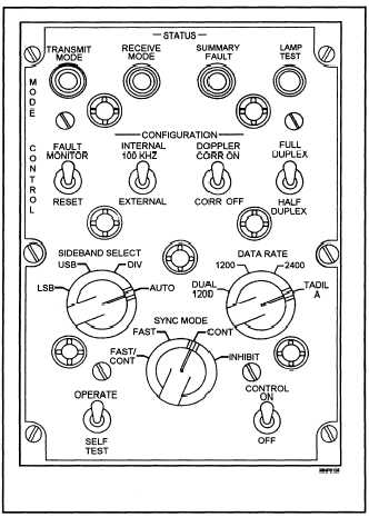
Figure 2-15.—The AN/USQ-59 Mode Control panel.
DTS CONTROLS AND INDICATORS
Many parameters that affect the operation of the
DTS are under the operator’s control, whether the
station is operating as a picket or as the net control
station. Both the operator and the technician must be
familiar with the various controls and indicators
associated with the DTS. The AN/USQ-59 uses
several control panels that are usually mounted next
to the operator’s display console. These panels enable
the operator and the technician to control and monitor
the net operation.
The control panels include a Mode Control panel,
a TADIL A Control panel, and an Address Selection
Indicator panel. Although the AN/USQ-59 control
panels are used here to show the controls and
indicators of a Link-11 DTS, other data terminal sets
have similar controls.
DTS Mode Control Panel
The DTS mode control panel controls and
indicators are shown in figure 2-15. The following is
a summary of how the controls affect the operation of
the link and what the indicators mean.
TRANSMIT MODE INDICATOR— Lights
when the DTS is in the transmit mode.
RECEIVE MODE INDICATOR— Lights when
the DTS is in the receive mode.
SUMMARY FAULT INDICATOR— Lights
when a fault in the DTS is detected while the DTS is
in the OPERATE mode. There are 27 performance
monitor fault-sensing circuits in the data converter
(modem) of the DTS. During the OPERATE mode,
14 of these sensors can cause a summary fault. The
fault-sensing circuits monitor areas such as various
power supplies, signal quality, preamble presence,
timing, and audio signal quality. When the DTS is in
SELF TEST, the summary fault lamp is lighted when
a fault is isolated to a function defined by switch
positions on the fault isolation control and built-in
tests routines.
LAMP TEST BUTTON— Causes all indicators
on the mode control panel, the TADIL A control
panel, and the address control unit to light.
FAULT MONITOR/RESET SWITCH— In the
MONITOR position, this switch allows the fault-
sensing function of the DTS to operate normally and
provide a fault summary signal to the DTS control.
When the switch in placed in the RESET position, the
fault-sensing circuits of the DTS are reset. The
SUMMARY FAULT lamp is turned off when the
fault-sensing circuits are reset.
INTERNAL 100 KHZ/EXTERNAL SWITCH-
Allows for the selection of the internal or external
100-kHz frequency standard.
DOPPLER CORR ON/CORR OFF SWITCH-
Enables the DTS Doppler correction when placed in
the CORR ON position.
2-13