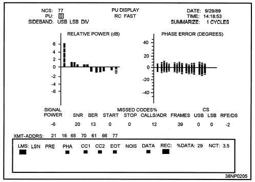
Figure 3-12.—The LMS-11 PU Display mode.
REL 605.— This column indicates the relative
power of the 605-Hz tone with respect to the average
power of the 15 data tones, measured in dB. It should
be +6 dB.
VAR DATA.— This is the variation of power in
the data tones in dB. The relative power of each of
the data tones, with respect to the average power of
the data tones, is determined. The variation is the
difference between the maximum and the minimum.
Under ideal conditions, the variation is zero. The
TADIL A specification for maximum variation is 1.5
dB l
PHASE ERR M.— This is the mean, or average,
phase error of the data tones. The intelligence is
stored in the data tones by use of the phase differences
that are odd multiples of 45 degrees. If the phase
difference of a data frame is 50 degrees when the
expected difference is 45 degrees, the error is
5 degrees. The phase errors for each tone are added
up, and after the specified number of cycles, the sum
for each tone is divided by the number of frames to
obtain the mean phase error for each tone. The mean
phase error for all 15 tones is then summed and
divided by 15 to obtain the value displayed.
PHASE ERROR SD.— This is the standard
deviation of the phase error in all 15 tones.
RFE/DS.— This is the radio frequency error, or
Doppler shift, measured in Hertz. If the Doppler
correction was enabled during the LMS-11
initialization, the value is color-coded green. If the
Doppler correction is turned off, this value is color-
coded cyan.
NCT.— This is the net cycle time, as measured
from phase reference frame to phase reference frame,
of the reporting unit. Note that this measure of net
cycle time is different from that used in other NCT
calculations.
PU Display
The PU display shows detailed information about
the signal received from the specified PU. The PU
display can operate in Broadcast, Short Broadcast, and
Roll Call modes. In Broadcast and Short Broadcast,
the display is updated after every transmission. In the
Roll Call mode, the display is updated after the
specified number of net cycles or 200 transmissions,
3-15