inside a cylinder of the engine. The events are
(1) intake, where a mixture of air and fuel is drawn
into the cylinder; (2) compression, where the
mixture is squeezed into a much smaller volume;
(3) power (or combustion), where the mixture is
burned; and (4) exhaust, where the burned
fuel/air mixture is forced from the cylinder. Now
consider the gas turbine engine.
The gas turbine engine operates on the
Brayton cycle (fig. 6-9, view B). The Brayton
cycle consists of the same four events as the Otto
cycle. However, all four events occur at the same
time, but in different locations within the gas
turbine engine.
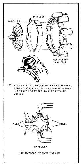
Figure 6-10.—Centrifugal compressor.
During the Brayton cycle, air enters the inlet
(1) at atmospheric pressure and constant volume.
As the air passes through the compressor (2), it
increases in pressure and decreases in volume. In
the combustor (3), the air mixes with fuel and
burns. During combustion, pressure remains
constant, but the increased temperature causes a
sharp increase in volume. The gases at constant
pressure and increased volume enter the turbine
(4) and expand through it. As the gases pass
through the turbine rotor, the rotor turns kinetic
and thermal energy into mechanical energy to do
work. The gases are released through the exhaust
(5), with a large drop in volume and at constant
pressure. The cycle is now completed.
GAS TURBINE ENGINE
TYPES AND CONSTRUCTION
There are two primary means of classifying
gas turbine engines: (1) by the type of compressor
used and (2) by how the power is used.
CENTRIFUGAL COMPRESSOR
The centrifugal compressor draws in air at the
center or eye of the impeller and accelerates it
around and outward. It consists of an impeller,
a diffuser, and a compressor manifold. The
diffuser is bolted to the manifold, and often the
entire assembly is referred to as the diffuser. For
ease of understanding, we will treat each unit
separately.
The impeller may be either single entry or dual
entry (fig. 6-10). The principal differences between
the single entry and dual entry are the size of the
impeller and the ducting arrangement. The single-
entry impeller (fig. 6-10, view A) permits ducting
directly to the inducer vanes, as opposed to the
more complicated ducting needed to reach the rear
side of the dual-entry type. Although slightly more
efficient in receiving air, single-entry impellers
must be of greater diameter to provide sufficient
air.
Dual-entry impellers (fig. 6-10, view B) are
smaller in diameter and rotate at higher speeds
to ensure sufficient airflow. Most gas turbines of
modern design use the dual-entry compressor to
reduce engine diameter. A plenum (an enclosure
in which air is at a pressure greater than that out-
side the enclosure) chamber is also required for
dual-entry compressors, since the air must enter
the engine at almost right angles to the engine axis.
The air must surround the compressor at positive
pressure to give positive flow.
6-6


