Some slippage is necessary for operation of
the hydraulic coupling, since torque is transmitted
because of the principle of relative motion
between the two rotors. The power loss resulting
from the small amount of slippage is transformed
into heat that is absorbed by the oil in the system.
Compared with mechanical clutches, hydraulic
clutches have a number of advantages. There is
no mechanical connection between the driving and
driven elements of the hydraulic coupling. Power
is transmitted through the coupling very efficiently
(97 percent) without transmitting torsional
vibrations or load shocks from the engine to the
reduction gears. This arrangement protects the
engine, the gears, and the shaft from sudden
shock loads that may occur as a result of piston
seizure or fouling of the propeller. The power is
transmitted entirely by the circulation of a driving
fluid (oil) between radial passages in a pair of
rotors. In addition, the assembly of the hydraulic
coupling will allow for slight misalignment.
PROPELLER
The screw-type propeller consists of a hub and
blades all spaced at equal angles about the axis.
When the blades are integral with the hub, the
propeller is known as a solid propeller. When the
blades are separately cast and secured to the hub
with studs, the propeller is known as a built-up
propeller.
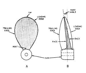
Some of the parts of the screw propeller are
identified in figure 8-9. The face (or pressure face)
is the afterside of the blade when the ship is
moving ahead. The back (or suction back) is the
surface opposite the face. As the propeller rotates,
the face of the blade increases pressure on the
Figure 8-9.—Propeller blade.
water to move it in a positive astern movement.
The overall thrust, or reaction force ahead, comes
from the increased water velocity moving astern.
The tip of the blade is the most distant from
the hub. The root of the blade is the area where
the blade joins the hub. The leading edge is the
edge that first cuts the water when the ship is
going ahead. The trailing edge (also called the
following edge) is opposite the leading edge.
A rake angle exists when the tip of the
propeller blade is not precisely perpendicular to
the axis (hub). The angle is formed by the distance
between where the tip really is (forward or aft)
and where the tip would be if it were in a
perpendicular position.
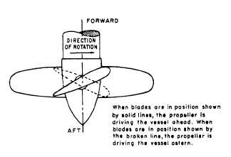
A screw propeller may be broadly classified
as either fixed pitch or controllable pitch. The
pitch of a fixed-pitch propeller cannot be altered
during operation. The pitch of a controllable-pitch
propeller can be changed at any time, subject to
bridge or engine-room control. The controllable-
pitch propeller can reverse the direction of a ship
without requiring a change of direction of the
drive shaft. The blades are mounted so that each
one can swivel or turn on a shaft that is mounted
in the hub (as shown in fig. 8-10).
SUMMARY
This chapter has provided you with some basic
information on several types of propulsion
systems used on Navy ships. You should become
familiar with the propulsion system on your ship.
Keep in mind, the propulsion systems are usually
a little different from ship to ship.
Figure 8-10.—Schematic diagram of a controllable-pitch
propeller.
8-8