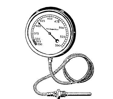
Figure 11-13.—Distant-reading, Bourdon-tube thermometer.
There are two basic types of filled-system
thermometers. One type has a Bourdon tube that
responds primarily to changes in the volume of the
filling fluid. The other type has a Bourdon tube that
responds primarily to changes in the pressure of the
filling fluid.
A distant-reading thermometer (fig. 11-13) consists
of a hollow metal sensing bulb at one end of a small-bore
capillary tube. The tube is connected to a Bourdon tube
or other device that responds to volume changes or
pressure changes. The system is partially or completely
filled with a fluid that expands when heated and
contracts when cooled. The fluid may be a gas, an
organic liquid, or a combination of liquid and vapor.
PYROMETERS
Pyrometers are used to measure temperature
through a wide range, generally between 300°F and
3,000°F. Aboard ship, pyrometers are used to measure
temperatures in heat treatment furnaces, the exhaust
temperatures of diesel engines, and other similar
purposes.
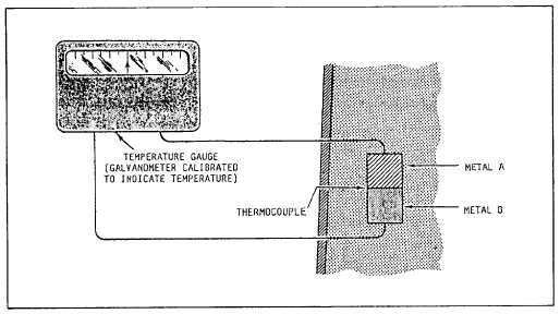
The pyrometer consists of a thermocouple and a
meter (fig. 11- 14). The thermocouple is made of two
dissimilar metals joined together at one end. It produces
an electric current when heat is applied at its joined end.
The meter, calibrated in degrees, indicates the
temperature at the thermocouple.
ELECTRICAL TEMPERATURE
MEASURING DEVICES
On newer propulsion plants, you will monitor
temperature readings at remote locations. Expansion
thermometers provide indications at the machinery
locations or on gauge panels in the immediate
thermometer area. To provide remote indications at a
central location, electrical measuring devices along with
signal conditioners are used. The devices discussed in
this section include the resistance temperature detectors
(RTDs), resistance temperature elements (RTEs), and
Figure 11-14.—Diagram arrangement of a thermocouple.
11-7