the cavity between the male rotor lobes and into the
grooves of the female rotor. The air is trapped in these
grooves, or pockets, and follows the rotative direction
of each rotor. As soon as the inlet port is closed, the
compression cycle begins as the air is directed to the
opposite (discharge) end of the compressor. The rotors
mesh, and the normal free volume is reduced. The
reduction in volume (compression) continues with a
resulting increase in pressure, until the closing pocket
reaches the discharge port.
The entrained water is removed from the discharged
air by a combined separator and water holding tank. The
water in the tank passes through a seawater-cooled heat
exchanger. The cooled water then recirculates to the
compressor for reinfection.
During rotation and throughout the meshing cycle,
the timing gears maintain the correct clearances
between the rotors. Since no contact occurs between the
rotor lobes and grooves, between the rotor lobes and
casing, or between the rotor faces and end walls, no
internal oil lubrication is required. This design allows
the compressor to discharge oil-free air.
For gear and bearing lubrication, lube oil from a
force-feed system is supplied to each end of the
compressor. Mechanical seals serve to keep the oil
isolated from the compression chamber.
RECIPROCATING TYPE.– All reciprocating air
compressors are similar to each other in design and
operation. The following discussion describes the basic
components and principles of operation of a
low-pressure reciprocating air compressor.
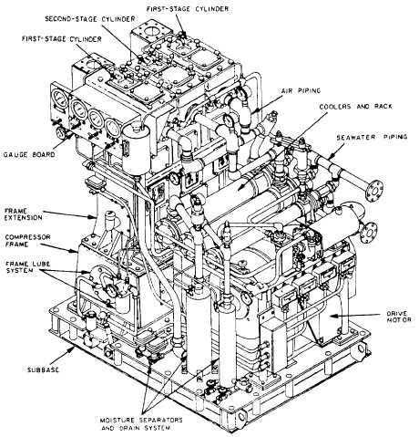
The LPAC is a vertical, two-stage single-acting
compressor that is belt-driven by an electrical motor.
Two first-stage cylinders and one second-stage cylinder
are arranged in-line in individual blocks mounted to the
crankcase (frame) with a distance piece (frame
extension). The crankcase is mounted on a subbase that
supports the motor, moisture separators, and a rack
assembly. The intercooler, aftercooler, freshwater heat
exchanger, and freshwater pump are mounted on the
rack assembly. The subbase serves as the oil sump.
Figure 10-25 shows the general arrangement of the
reciprocating-type compressor.
Figure 10-25.—LPAC (reciprocating type).
10-27

