Figure 9-31.—Valve manifold showing cutaway view of the
valves and typical combination of suction and discharge
valves.
When the pressure in the valve reaches 1500 psi,
the poppet reaches the end of its travel. As the
pressure increases, the piston continues to move
to the right, which unseats the poppet and allows
flow through the valve, as shown in view A of
figure 9-30. If the pressure drops below 1500 psi,
the compressed spring forces the piston to the left,
the poppet seats, and flow through the valve
stops.
Figure 9-30, view B, shows the priority valve
in the free-flow position. The flow of fluid moves
the poppet to the left, the poppet spring
compresses, and the poppet unseats. This allows
free flow of fluid through the valve.
VALVE MANIFOLDS
Sometimes suction must be taken from one of
many sources and discharged to another unit or
units of either the same or another group. A valve
manifold is used for this type of operation. An
example of such a manifold (fig. 9-31) is the fuel
oil filling and transfer system where provision
must be made for the transfer of oil from any tank
to any other tank, to the service system, or to
another ship. If, for example, the purpose is to
transfer oil from tank No. 1 to tank No. 4, the
discharge valve for tank No. 4 and the suction
valve from tank No. 1 are opened, and all other
valves are closed. Fuel oil can now flow from tank
No. 1, through the suction line, through the
pump, through the discharge valve, and into tank
No. 4. The manifold suction valves are often of
the stop-check type to prevent draining of pumps
when they are stopped.
VALVE HANDWHEEL IDENTIFICA-
TION AND COLOR CODING
Valves are identified by markings inscribed on
the rims of the handwheels, by a circular label
plate secured by the handwheel nut, or by label
plates attached to the ship’s structure or to the
adjacent piping.
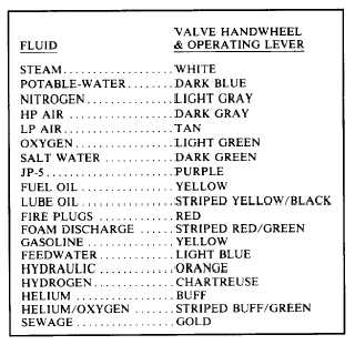
Piping system valve handwheels and operating
levers are marked for training and casualty
control purposes with a standardized color code.
Color code identification is in conformance with
the color scheme of table 9-1. Implementation of
Table 9-1.—Valve Handwheel Color Code
9-21