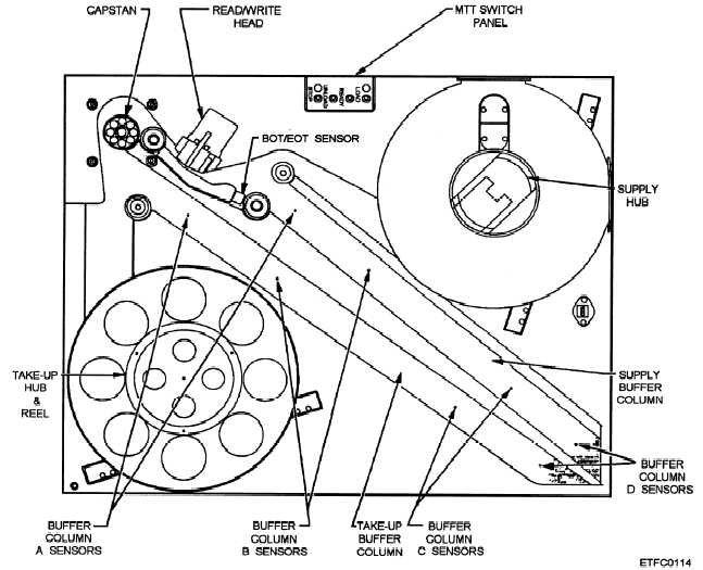
Figure 9-19.—A magnetic tape transport, detailed view.
Figure 9-19 shows a common form of tape transport.
The supply and take-up reels are mounted on
servo-driven hubs. The tape is guided from the supply
reel through the supply vacuum column, under the
read/write head, over the capstan, through the take-up
vacuum column, to the take-up reel.
Loops of tape are formed in the vacuum columns
during the loading process. The size of the tape loop in
the vacuum column determines the direction of rotation
of the servomotor-driven reel that corresponds to the
column (supply/take-up).
The capstan determines the direction and speed of
tape movement under the read/write head assembly.
The capstan is driven by a bidirectional motor so that it
may rotate in either direction. When tape motion is
desired, the capstan is rotated in the desired direction.
Natural friction or vacuum applied through holes in the
capstan pulls the tape in the desired direction at the
correct speed. Tachometers are often used to sense for
correct tape speed and to control capstan speed.
As the capstan pulls the tape, tape is “taken up” from
one vacuum column, and “payed out” into the other.
Tape position in the columns is sensed by
pressure-sensitive switches or photodiode assemblies.
As one column is being emptied of its tape loop, the
corresponding servo-driven reel pays out tape to
maintain the correct tape loop. As the loop in the
opposite column grows larger, the corresponding
servo-driven reel takes up tape, once again maintaining
the correct size loop. The locations of loop sensors in
the vacuum column and servo-hub response are shown
in figure 9-20.
The MTT must be connected to the MTU control
unit and power supply for the necessary operational
commands and power.
MTT Block Diagram
The MTT can be divided into the following
functional areas, as shown in figure 9-21:
9-16


