provide power throughout the computer. For example,
we want a signal to go from a CPU module or pcb to a
memory module or pcb. A signal will leave the CPU at
its plug, which is plugged into a connector receptacle.
A conductor will route that signal from the CPU’s
connector receptacle to the memory’s connector
receptacle, where the signal will go from the connector
plug to its destination inside a memory module or pcb.
INTERNAL CONNECTOR RECEP-
TACLES. —Internal connector receptacles receive the
connector plug of an individual unit (module,
subassembly, or pcb) or wiring harness. Connector
receptacles can have male or female electrical contacts.
The sizes and shapes of the electrical contacts vary.
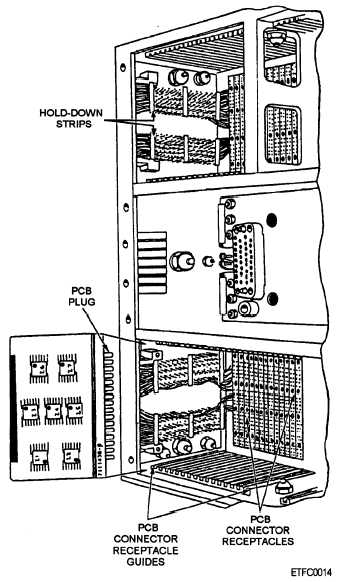
Figure 2-23.—Connector receptacle of a module for a pcb.
Refer to your computer’s technical manual for details.
Receptacle connectors are used in the following places:
Frame or cabinet to receive a module or wiring
harness
Module to receive a subassembly or pcb
Chassis or assembly to receive a subassembly or
pcb
Rack or cage to receive a pcb
Motherboard or backplane to receive a pcb
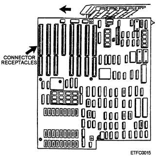
Examples of connector receptacles are illustrated in
figures 2-23 and 2-24. Figure 2-23 shows the connector
receptacles of a module for receiving pcb’s. Figure
2-24 illustrates the connector receptacles of a
motherboard.
INTERNAL CONNECTOR PLUGS.—
Individual units and wiring harnesses will have a plug
that connects into an internal connector receptacle.
Again depending on the design, the plug can have male
or female electrical contacts. The connector plugs on
the following units will be plugged into connector
receptacles:
Module
Subassembly
Pcb
Wiring harness
Figure 2-24.—Connector receptacles of a motherboard.
2-19


