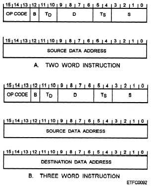
D (bits 29 through 26 is a code identifying the destina-
tion portion of the instruction. S (bits 23 through 20)
identifies the source portion. TD (bits 211 and 210)
and TS (bits 25 and 24 are bits in the instruction word
that identify the type of addressing mode being used to
locate the destination and source addresses.
As shown in figure 8-4, two or three memory words
are required for some instructions depending on the
addressing mode indicated by TD and TS. Addressing
modes are discussed in the next section.
Microcomputers may have more than one instruction
format for the one word instructions. The format
depends on the type of instruction being used.
Mainframe Computer Instruction Formats
The instruction formats for large mainframe
computers vary greatly between types, generations, and
manufacturers of computers. For our example, we
selected the instruction format for CPU instructions of
a mainframe computer with 32-bit computer
instructions. These instructions can have up to seven
basic formats designated I, II, III, IV-A, IV-B, IV-C and
V. The majority of these instructions are full memory
word (32-bit) instructions. Only formats IV-A, IV-B,
Figure 8-4.—Microcomputer instruction formats with two
and three memory words.
and IV-C are upper or lower half-word (16-bit)
instructions.
The instructions are divided into a number of single
or multibit fields that each perform a specific function
during instruction execution. Two fields called the
function code (f) and the accumulator or index (a)
designator fields are consistent throughout all the
formats. The f field is the 6-bit function code (op code)
and the a field is the 3-bit accumulator register
designator field.
The function code (f) defines the complete
operation to be performed or it may be used in
conjunction with other fields called subfunction
designators to define an operation. The accumulator
register designator (a) field is used to identify the
particular accumulator (0-7), index (0-7), or stack
pointer register (0-7) needed for the operation. The
formats and instruction fields are described in the
following paragraphs.
Formats I, II, and III —These three formats (fig.
8-5) make up the majority of instructions in the example
computer’s repertoire of instructions. Format I
instructions perform the basic load, store, replace, and
simple mathematical operations for the computer.
Format II instructions are concerned with single
precision mathematics, interrupt, and I/O commands.
Format III instructions are used for program sequence
control (jumps, return jumps, and switch controlled or
manual jumps).
The three formats have many fields in common.
The nine most significant bits (231 through 223) are
made up of the f and a fields. Only bits 222 through 220
differ between the three formats. In format I, the 3-bit
field is called the k field or operand interpretation
designator. This field is used primarily during
mathematical operations. In format II instructions, the
three bits become a subfunction code (f2). And in
format III instructions, the three bits become a two-bit
subfunction code (f3) and a single-bit k code that is
always ZERO for format III instructions.
NOTE: Subfunction codes, f2 through f6 are used
as part of the op code unless otherwise specified. A
subfunction code of two bits has a maximum value of
3 (112). A subfunction code of three bits has a
maximum value of 7 (1112). For example, the format
II op code 07 could have a subfunction 7 and format III
op code 53 could have a subfunction code of 3.
The remainder of the instruction, bits 219 through
20, is the same for all three formats. There is a 3-bit
index register designator code (b), a single-bit indirect
8-8


