graph to provide the collimation error similar to the
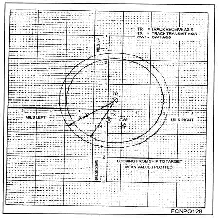
is plotted together on a beam position summary graph,
TX procedures. Usually, a 15-mil excursion each side
as shown in figure 4-9. From their relative positions,
of the maximum power point is sufficient. After all
the collimation errors can be determined and any cor-
three RF beam axes have been established, their data
rective action, if required, can be made.
Figure 4-9.—Beam position summary graph.
4-9

