RCV DATA ERROR INDICATOR— This
indicator is lighted when the DTS detects an error in
received data being sent to the CDS computer.
CODE ERROR INDICATOR— The CODE
ERROR indicator is lighted when the DTS detects an
error in the received or sidetone (transmit) control
codes during TADIL A operations.
NET BUSY INDICATOR— The NET BUSY
indicator is lighted when the DTS detects that the
communications net is busy. It is activated when a
signal called signal presence is generated by the
DTS.
SYNC COMPT INDICATOR— The SYNC
COMPT indicator is lighted continuously, or flashes,
when the DTS has achieved synchronization with the
NCS data terminal.
TIMING STORED/CORRECTED SWITCH-
The TIMING STORED/CORRECTED switch
determines how the DTS is synchronized. When the
switch is in the CORRECTED position, the fast
synchronization
and/or
the
continuous
synchronization circuitry in the DTS is used. The
position of the sync mode switch on the mode control
panel determines whether the fast, continuous, or both
circuits are used to maintain synchronization. When
the switch is in the STORED position, the DTS uses
the time base stored during Net Sync. During normal
operations, this switch should be in the CORRECTED
position.
OPERATE/RADIO SILENCE SWITCH— The
OPERATE/RADIO SILENCE switch is a two-
position toggle switch that allows the DTS to inhibit
radio transmissions.
When the switch is in the
OPERATE position, the DTS operates normally.
When the switch is switched to the RADIO SILENCE
position, the radio keyline and transmit audio circuits
are immediately disabled.
NET CONTROL/PICKET SWITCH— The
NET CONTROL/PICKET switch configures the DTS
to operate as the net control station or a picket station
in Roll Call mode.
ERROR CORRECT/LABEL SWITCH.— The
ERROR CORRECT/LABEL switch determines how
the DTS processes detected errors. When the switch
is in the CORRECTED position, the DTS attempts to
correct detected errors.
If a single bit error is
detected, the location of the erroneous bit is detected
and corrected. If an even number of bit errors occurs,
the correction circuitry is inhibited. If an odd number
of bit errors occurs, the correction circuitry attempts
to correct the data; however, if an odd number of
multiple bit errors occurs, an erroneous correction is
made. When the switch is in the LABEL position, the
DTS does not attempt to correct detected errors.
Instead, the data word sent to the computer is labeled
to indicate that errors were detected in the data word.
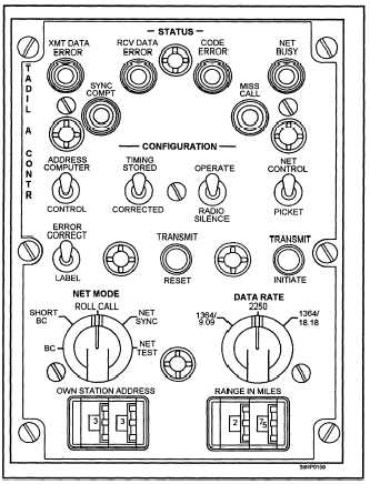
Figure 2-16.—The AN/USQ-59 TADIL A control panel.
TRANSMIT
RESET
SWITCH— The
TRANSMIT RESET switch is a momentary contact
pushbutton switch.
When depressed, this switch
causes any transmission in progress to be terminated.
The DTS stops the transmission by inhibiting the
generation of the output data request, causing a stop
2-15