distance. This allows the operator to view the effects
of the noise. The power of the noise tones is also
indicated by open yellow bars.
To enter the spectrum display, depress the SPECT
key on the keyboard. Several options are available to
the operator by entering data into the header fields of
the spectrum display. The operator may designate the
address of the NCS. The default address is 77. The
operator can also select a particular sideband (USB,
LSB, or DIV) for display. By using the RESTRICT
field, the operator can restrict the display to only data
frames or only preamble frames, or choose no
restrictions.
The PU field allows the operator to
designate a particular PU for display. If 00 is entered
into the PU field, the data display is continuously
updated with samples from the entire net.
Carrier Suppression Display
The carrier suppression display measures how
successfully the carrier frequency is suppressed. The
carrier suppression measurements can only be made
during Net Sync. To measure the carrier suppression,
the radio must be off-tuned by -500 Hz for the upper
sideband and +500 Hz for the lower sideband. This
off-tuning allows the program to measure and
compare the relative power of the carrier frequency
and the 605-Hz tone of the preamble.
RECOGNIZING LINK-11 NET PROBLEMS
The LMS-11 is very useful in evaluating Link-11
net quality. As you have seen, the various on-line
modes can help you determine various problems.
These include a station that is consistently missing
call-ups, poor signal-to-noise ratio, and low power
from a unit. Some common Link-11 problems and the
LMS-11 display are covered in the next few
paragraphs.
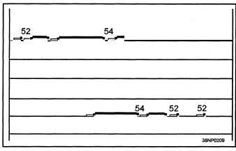
Figure 3-14 shows an example of how a PU not
responding to call-ups would appear on the LMS-11
operating in the Link Monitor mode. When a PU
does not respond to a call-up, the reason maybe that
the incorrect PU number was entered at the NCS or at
the DTS of the unit. It can also be caused by a poor
receiver at the PU, causing the PU to not receive its
call-up. A third problem could be a weak transmitter
at the PU, causing the NCS to not receive the
response and therefore, repelling the PU.
Figure 3-14.—A PU not responding to NCS call-up.
Figure 3-15 shows the display that appears when
a PU is responding to NCS call-ups, but the report
contains no data. Causes of this problem could be
that the KG-40 has an alarm, the CDS program is
down, or the problem is in the CDS computer to DTS
patching.
Figure 3-15.—A PU responding with no data.
When the NCS fails to receive a stop code from a
PU, a stoppage of the net occurs, as shown in figure
3-16. If this condition occurs repeatedly and can be
traced to a single PU, the NCS should delete the PU
until the stop code problem in the DTS is corrected.
Figure 3-16.—A net stoppage caused by NCS not receiving
a stop code.
Figure 3-17 shows several PUs not responding to
call-ups. Some of the causes for this condition could
3-18


