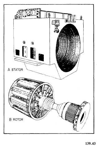
Figure 12-2.—Low-speed, engine-driven alternator.
l Only two slip rings are necessary to supply
excitation to the revolving field.
l The stator winding is not subjected
to mechanical stresses that are due to
centrifugal force.
The ac generators (alternators) used by the
Navy are divided into two classes: (1) low-speed,
engine-driven alternators and (2) high-speed,
turbine-driven alternators.
The low-speed, engine driven alternator
(fig. 12-2) has a large diameter revolving field,
with many poles, and a stationary armature. The
stator (view A) contains the armature windings.
The rotor (view B) consists of protruding poles
on which the dc field windings are mounted.
The high-speed alternator may be either steam-
er gas-turbine driven. The high-speed, turbine-
driven alternator (fig. 12-3) is connected either
directly or through gears to a steam turbine. The
Figure 12-3.—High-speed, turbine-driven alternator.
enclosed metal structure is part of a forced
ventilation system that carries away the heat by
circulating air through the stator (view A) and
rotor (view B).
SHIP’S SERVICE TURBINE-DRIVEN
GENERATORS
Ship’s service generators furnish electricity
for the service of the ship. Aboard most steam-
driven ships of the Navy, these generators
are driven by turbines. Large ships may have
as many as six or eight ship’s service generators
and from one to three emergency diesel-driven
alternators.
New cruisers and destroyers have three gas-
turbine-driven ship’s service generators and
smaller diesel-driven emergency generators. These
generators are located in three different compart-
ments and separated by at least 15 percent of the
length between perpendiculars to make sure they
survive.
12-3