are maintained at that position either manually or by
automatic tracking circuits.
You need to be familiar with two types of bearing:
true and relative.
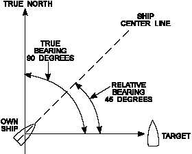
TRUE BEARING.—True bearing is the angle
between true north and a line pointed directly at the
target. This angle is measured in the horizontal plane
and in a clockwise direction from true north.
RELATIVE BEARING.—Relative bearing is the
angle between the centerline of the ship and a line
pointed directly at the target. This angle is measured in
a c l o c k w i s e d i r e c t i o n f r o m t h e b ow.
M o s t
surface-search radars provide only range and bearing
information. Both true and relative bearing angles are
illustrated in figure 1-2.
Altitude
Altitude or height-finding radars use a very narrow
beam in the vertical plane. This beam is scanned in
elevation, either mechanically or electronically, to
pinpoint targets. Tracking and weapons-control radar
systems in current use scan the beam by moving the
antenna mechanically or the radiation source
electronically.
Most air-search radars use electronic elevation
scanning techniques.
Some older air-search radar
systems use a mechanical elevation scanning device;
but these are being replaced by electronically scanning
radar systems.
RADAR TRANSMISSION METHODS
Radar systems are normally divided into two
operational categories (purposes) based on their
method of transmitting energy. The most common
method, used for applications from navigation to fire
control, is the pulse-modulation method. The other
method of transmitting is continuous-wave (CW).
CW radars are used almost exclusively for missile
guidance.
Pulse Modulation
In the pulse method, the radar transmits the RF in a
short, powerful pulse and then stops and waits for the
return echo. By measuring the elapsed time between
the end of the transmitted pulse and the received echo,
the radar can calculate a range. Pulse radars use one
antenna for both transmitting and receiving. While the
transmitter is sending out its high-power RF pulse, the
antenna is connected to the transmitter through a
special switch called a duplexer.
As soon as the
transmitted pulse stops, the duplexer switches the
antenna to the receiver.
The time interval between
transmission and reception is computed and converted
into a visual indication of range in miles or yards.
Pulse-radar systems can also be modified to use the
Doppler effect to detect a moving object. The Navy
uses pulse radars to a great extent.
Continuous Wave
In a CW radar the transmitter sends out a
“continuous wave” of RF energy. Since this beam of
RF energy is “always on”, the receiver requires a
separate antenna. One disadvantage of this method is
that an accurate range measurement is impossible
because there is no specific “stop time”. This can be
overcome, however, by modulating the frequency. A
frequency-modulated continuous wave (FM-CW)
radar can detect range by measuring the difference
between the transmitted frequency and the received
frequency. This is known as the “Doppler effect”. The
c o n t i n u o u s - wave m e t h o d i s u s u a l l y u s e d b y
fire-control systems to illuminate targets for missile
systems.
RADAR SYSTEM ACCURACY
To be effective, a radar system must provide
accurate indications.
That is, it must be able to
determine and present the correct range, bearing, and,
in some cases, altitude of an object. The degree of
accuracy is primarily determined by two factors: the
r e s o l u t i o n o f t h e r a d a r s y s t e m a n d ex i s t i n g
atmospheric conditions.
1-4
Figure 1-2.—True and relative bearings.