Radar Receiver Mixers
Many radar receivers do not use the RF amplifier
stage; instead, they use a crystal mixer stage as the
receiver front end. If an RF amplifier is used, the
design is critical, because the weak signal levels may
easily be masked by noise generated by components
in the RF amplifier. LNAs have solved some of the
noise problems, but they are not in wide use in radar
applications.
The simplest type of radar mixer is the single-
ended, or unbalanced, crystal mixer. The mixer uses
a tuned section of coaxial transmission line that is
one-half wavelength long and matches the crystal to
the signal echo and the local oscillator (LO) inputs.
Local oscillator injection is accomplished by a probe,
while the signal is injected by a slot in the coaxial
assembly. This slot is normally inserted in the du-
plexer waveguide assembly and properly oriented to
provide coupling of the returned signal. In this appli-
cation, the unwanted signals at the output of the mixer
(the carrier, the local oscillator, and the sum of these
two signals) are effectively eliminated by a resonant
circuit tuned to the intermediate, or difference, fre-
quency.
One advantage of the unbalanced crystal mixer is
its simplicity. It has, however, one major disadvantage
—its inability to cancel LO noise. Since a klystron
generates a high degree of noise, it makes it difficult
to detect weak signals if that noise is allowed to pass
through the mixer along with the signal.
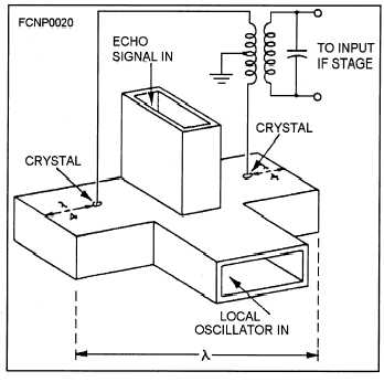
One type of mixer that cancels LO noise is the
balanced hybrid mixer (sometimes called the magic
T), shown in figure 2-14. In hybrid mixers, crystals
are inserted directly into the waveguide one-quarter
wavelength from their respective short-circuited
waveguide ends. This is a point of maximum voltage
along a tuned line. The crystals are also connected to
a balanced transformer, the secondary of which is
tuned to the desired IF.
Figure 2-14.—Balanced hybrid crystal mixer.
Since there is a difference in phase between echo
signals applied across the two crystals, and because
the signal applied to the crystals from the LO is in
phase, there will be a condition when both signals ap-
plied to crystal number 1 will be in phase, and the
signals applied to crystal number 2 will be out of
phase. This means that an IF signal of one polarity
will be produced across crystal number 1, and an IF
signal of the opposite polarity will be produced across
crystal number 2. When these two signals are applied
to the balanced output transformer, they will add.
Outputs of the same polarity will cancel across the
balanced transformer.
It is this action that eliminates the LO noise. Noise
components that are introduced from the LO are in
phase across the crystals and are canceled in the
balanced transformer. It is necessary that the RF ad-
mittances of the crystals be nearly equal or the LO
noise will not completely cancel. Only the noise pro-
duced by the LO is canceled; noise arriving with the
echo signal is not affected.
2-25


