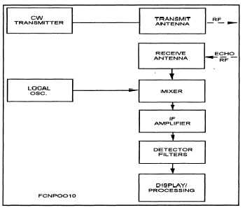
The simple CW radar has the same basic com-
ponents found in pulse radars; the main difference is
the use of a separate antenna to receive and the use of
filters to detect a Doppler shift. The filters are nor-
mally designed for the IF range, since working at the
transmitter frequencies is more critical in the con-
struction of circuits. The filters are set up to detect a
particular narrow frequency band. The bands are set
so they are adjacent to each other and cover the
expected Doppler frequencies above and below the
zero shift. The narrower the filter bandwidth, the more
filters are required and the more discrete velocities
can be determined within the receiver bandwidth.
With the basic CW radar, target range cannot be
determined. However, a target can be tracked by the
angle method. Angle resolution is determined the
same way for both CW and pulse radars.
CW radars have an advantage over pulse radars
when detecting moving targets in clutter. This is very
useful when the clutter is caused by chaff, since detec-
tion is based on the Doppler frequency and not on a
return pulse. With a simple CW radar, it is almost im-
possible to detect a stationary target because of clutter
and leakage at the transmitter frequency. Moving tar-
gets are easily detected, but range determination is
more difficult. A diagram of a basic CW radar is
shown in figure 2-4.
Figure 2-4.—Basic CW radar.
FM-CW Radar System
The limitation of being unable to determine target
range with C W radars can be overcome by frequency
modulating the transmitted signal. The resulting radar
is the frequency-modulated, continuous-wave (FM-
CW) radar.
The transmitter still transmits continuously, but
the frequency is changed in a predetermined fashion.
The modulation can be in the form of a sawtooth, tri-
angular, sinusoidal, or other shape as long as it pro-
duces a frequency change of known rate.
SCANNING METHODS
For a radar to track a target, some means of keep-
ing the radar beam pointed at the target is required.
The radar system must be able to determine in which
direction the radar beam must be moved so that the
target remains in the center of the beam. A visual
indication on the CRT can depict range and angle of
the target in respect to the beam center. The operator
can then move the beam by positioning the antenna
center on the target. Today’s radar systems use com-
puter-aided automatic tracking systems. Their two
basic scanning methods are mechanical and electronic
scanning.
MECHANICAL SCANNING
Mechanical scanning can be flexible in that the
antenna can be moved in one of two desired patterns:
(1) The feed horn can be moved relative to a fixed
reflector, or (2) the reflector can be moved relative to
a fixed feed horn. The most common mechanical scan
technique used by fire-control radars is a movable
feed horn relative to a fixed reflector, which is called
conical scanning.
Included in mechanical scanning are nutation, nu-
tating waveguide, and angle tracking.
2-5


