netron so that the magnetic field is parallel with the
axis of the cathode. The cathode is mounted in the
center of the interaction space. The direction of an
electric field is from the positive electrode to the
negative electrode.
The law governing the motion of an electron in an
electric (E) field states that the force exerted by an
electric field on an electron is proportional to the
strength of the field. Electrons tend to move from a
point of negative potential toward a positive potential.
In other words, electrons tend to move against the E
field. When an electron is being accelerated by an E
field, energy is taken from the field by the electrons.
The law of motion of an electron in a magnetic
(H) field states that the force exerted on an electron in
a magnetic field is at right angles to both the field and
the path of the electron. The direction of the force is
such that the electron trajectories are clockwise when
viewed in the direction of the magnetic field.
Magnetron oscillators are divided into two classes:
negative resistance and electron resonance.
. Negative Resistance: A negative resistance
magnetron oscillator operates by a static negative
resistance between its electrodes and has a frequency
equal to the natural period of the tuned circuit con-
nected to the tube. The split-anode negative resistance
magnetron is a variation of the basic magnetron,
which operates at a higher frequency and is capable of
more output.
. Electron Resonance: An electron resonance
magnetron oscillator operates by the electron transit-
time characteristics of an electron tube (the time it
takes electrons to travel from the cathode to the plate).
It is capable of generating very large peak-power out-
puts at frequencies in the thousands of megahertz. The
electron resonance magnetron is most widely used for
microwave frequencies.
Modern designs have a
reasonably high efficiency and relatively high output.
However, one disadvantage of the electron resonance
magnetron is that its average power is limited by the
cathode emission. Furthermore, the peak power is
limited by the maximum voltage that it can withstand
without damage.
The operation, coupling methods, tuning, and
seasoning of magnetrons are discussed in the fol-
lowing subsections. Since this information is general
in nature, the recommended times and PMS proce-
dures in equipment technical manuals should be
followed when baking-in a specific type of magne-
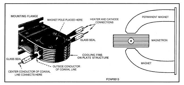
tron. Figure 2-7 shows a magnetron.
Figure 2-7.—Magnetron.
2-10


