spherical waves emerge at the exit side of the
conducting lens (lens aperture) as flat-fronted parallel
waves. This type of lens is frequency sensitive.
The dielectric type of lens, shown in figure 1-10,
view B, slows down the phase propagation as the wave
passes through it. This lens is convex and consists of
dielectric material. Focusing action results from the
difference between the velocity of propagation inside
the dielectric and the velocity of propagation in the air.
The result is an apparent bending, or refracting, of the
waves.
The amount of delay is determined by the
dielectric constant of the material.
In most cases,
artificial dielectrics, consisting of conducting rods or
spheres that are small compared to the wavelength, are
used. In this case, the inner portions of the transmitted
waves are decelerated for a longer interval of time than
the outer portions.
In a lens antenna, the exit side of the lens can be
regarded as an aperture across which there is a field
distribution. This field acts as a source of radiation,
just as do fields across the mouth of a reflector or horn.
For a returning echo, the same process takes place in
the lens.
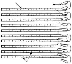
ARRAY ANTENNAS .—An array type of
antenna is just what the name implies—an array or
regular grouping of individual radiating elements.
These elements may be dipoles, waveguide slots, or
horns. The most common form of array is the planar
array, which consists of elements linearly aligned in
two dimensions—horizontal and vertical—to form a
plane (fig. 1-11).
Unlike the lens or parabolic reflector, the array
applies the proper phase relationship to make the
wavefront flat before it is radiated by the source feed.
The relative phase between elements determines the
position of the beam; hence the often used term,
phased array. This phase relationship is what allows
the beam to be rotated or steered without moving the
antenna. This characteristic of array antennas makes it
ideal for electronic scanning or tracking. (We will
discuss scanning shortly.)
Radomes
The term radome is a combination of the words
radar and dome.
Radomes are used to cover and
protect radar antennas from environmental effects such
as wind, rain, hail, snow, ice, sand, salt spray,
lightening, heat, and erosion.
The ideal radome is
transparent to the RF radiation from the antenna and its
return pulses and protects the antenna from the
environment.
A radome’s design is based on the
expected environmental factors and the mechanical
and electronic requirements of the RF antenna.
Although, in theory, a radome may be invisible to
RF energy, in real life the radome effects antenna’s
performance in four ways. These are; beam deflection,
transmission loss, reflected power, and secondary
effects. Beam deflection is the shift of the RF beam’s
axis. This is a major consideration with tracking (i.e.
FC) radar.
Transmission loss is the loss of energy
associated with reflection and absorption within the
radome. Reflected power can cause antenna mismatch
in small radomes and sidelobes in large radomes.
Depolarization and increased antenna noise are a result
of secondary effects.
As an FC, you will be primarily responsible
maintaining the radome associated with your
equipment.
This normally will include routine
cleaning and inspection according to your prescribed
preventive maintenance schedule. Some minor repairs
may be authorized by your technical manuals, but most
repairs will normally be done by an authorized factory
representative. You may be required to repaint the
radome because of normal environmental wear and
tear. If so, be especially careful to use only paint(s)
authorized by the manufacturer and to follow the
authorized step-by-step procedures.
Figure 1-12 is an example of a radome in use in
today’s Navy. Other systems that use radomes include,
the Combined Antenna System of the Mk 92 Fire
Control System, the AN/SPQ-9 series antenna for the
Mk 86 Gun Fire Control System, and the Mk 23 Target
1-10
HORIZONTAL LINEAR
SUBARRAY
TRANSMITTER AND RECEIVER
SLOT
ANTENNA
FCRf0111
Figure 1-11.—Planar array antenna.


