as a directional radiator. Horn radiators may be fed by
coaxial or other types of lines.
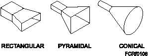
Horns are constructed in a variety of shapes, as
illustrated in figure 1-8. The shape of the horn, along
with the dimensions of the length and mouth, largely
determines the beam’s shape. The ratio of the horn’s
length to mouth opening size determines the
beamwidth and thus the directivity. In general, the
larger the opening of the horn, the more directive is the
resulting field pattern.
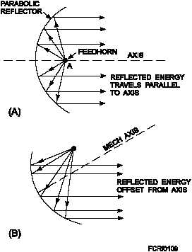
FEEDHORNS.—A waveguide horn may be used
to feed into a parabolic dish. The directivity of this
horn, or feedhorn, is then added to that of the parabolic
dish. The resulting pattern (fig. 1-9, view A) is a very
narrow and concentrated beam. Such an arrangement
is ideally suited for fire control use. In most radars, the
feedhorn is covered with a window of polystyrene
fiberglass to prevent moisture and dirt from entering
the open end of the waveguide.
One problem associated with feedhorns is the
shadow introduced by the feedhorn if it is in the path of
the beam. (The shadow is a dead spot directly in front
of the feedhorn.) To solve this problem the feedhorn
can be offset from center (fig. 1-9, view B). This takes
it out of the path of the RF beam, thus eliminating the
shadow.
LENS ANTENNA.—Another antenna that can
change spherical waves into flat plane waves is the lens
antenna. This antenna uses a microwave lens, which is
similar to an optical lens to straighten the spherical
wavefronts. Since this type of antenna uses a lens to
straighten the wavefronts, its design is based on the
laws of refraction, rather than reflection.
Two types of lenses have been developed to
provide a plane-wavefront narrow beam for tracking
radars, while avoiding the problems associated with
the feedhorn shadow.
These are the conducting
(acceleration) type and the dielectric (delay) type.
The lens of an antenna is substantially transparent
to microwave energy that passes through it. It will,
however, cause the waves of energy to be either
converged or diverged as they exit the lens. Consider
the action of the two types of lenses.
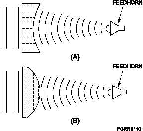
The conducting type of lens is illustrated in figure
1-10, view A. This type of lens consists of flat metal
strips placed parallel to the electric field of the wave
and spaced slightly in excess of one-half of a
wavelength. To the wave these strips look like parallel
waveguides. The velocity of phase propagation of a
wave is greater in a waveguide than in air. Thus, since
the lens is concave, the outer portions of the
transmitted spherical waves are accelerated for a
longer interval of time than the inner portion. The
1-9
Figure 1-9.—Reflector with feedhorn.
Figure 1-10.—Antenna lenses: A. Conducting (acceleration)
type of microwave lens; B. Dielectric (delay) type of
microwave lens.
Figure 1-8.—Horn radiators.


