across a track, the signal from the dipole bits are
summed. When the result of this summing equals zero,
or null, the heads are centered on track.
During a seek operation, the heads move across the
dibit tracks, a counter is incremented for each track
crossed. The heads continue to move until the counter
reaches the desired track.
DISK FILE UNIT CONTROLS AND
INDICATORS
The disk memory set can be controlled from several
control panels. These are as follows:
Operator’s panel
Status/maintenance panel
Disk status panel
Power supply panel
Operator’s Panel
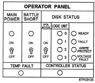
Atypical operator’s panel is shown in figure 10-11.
It contains the switches and indicators used to turn the
disk file or memory unit (MAIN POWER) and spindle
drive motor (SPDL MOTOR) on, and to indicate the
readiness of the disk drive (DISK STATUS) and
controller (CONTROLLER STATUS) during and after
the power on sequence.
The operator’s panel. also indicates the disk drive
address (LOGIC UNIT). The READY indicator is lit
when the disk rotation is up to speed, the heads are
loaded, and no-fault conditions exist. It also indicates
Figure 10-11.—A disk memory set operator’s panel.
when the disk is protected from a write operation by
switch action or fault condition (WRITE PROTECT).
In addition the FAULT indicator indicates the detection
of a variety of faults as defined by the STATUS/
MAINTENANCE PANEL fault indicators.
Status/Maintenance Panel
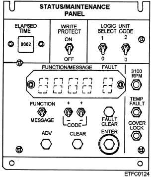
The status/maintenance panel, shown in figure
10-12, is found on the disk unit. The panel is controlled
by a microprocessor and contains the ELAPSED TIME
meter, the WRITE PROTECT (this unit’s drive only)
switch, the LOGIC UNIT SELECT CODE (disk drive
address 0, 1, 2, or 3) switches, and some fault and status
indicators for the disk drive (3,100 RPM, TEMP
FAULT, COVER LOCK) The 3,100 rpm indicator is
illuminated when the spindle has reached normal
rotation speed. TEMP FAULT indicates an abnormal
temperature condition. COVER LOCK indicates the
spindle is rotating more than 175 rpm and the shroud
cover is locked, a normal condition.
The remainder of the panel is used for operator
command entry and status message display readout.
The FUNCTION/MESSAGE digital display comprises
four digits of the five-element display. The
FUNCTION/MESSAGE readout is used to enter a large
variety of hexadecimal coded operator commands or
responses (FUNCTIONS), and for displaying controller
coded displays (MESSAGEs) for the operator or
Figure 10-12.—A status/maintenance panel (disk unit only).
10-15


