transmissions. In other words, both speeds are
converted using the same reference signal.
Synchro-to-Digital (S/D) Conversion
Two methods are currently in use to convert
synchro data to digital words (BAMs): the sector
method and the octant method. Both methods of
conversion require a reference voltage input for
conversion to take place.
SECTOR CONVERSION. —The sector
conversion method uses the reference voltage to
determine the time to sample the stator voltages for
conversion to take place. The ideal time to sample the
stator voltages is when the reference voltage is at or near
the positive or the negative peak of its cycle.
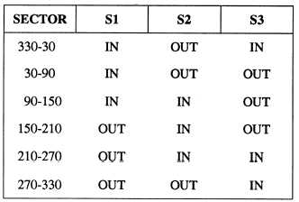
Sixty-Degree Sector Determination. —Once the
negative or the positive peak of the reference is
detected, the sector in which the rotor is positioned may
be determined. There are six 60-degree sectors within
the 360-degree rotation of the rotor. The relationship
of the stator voltages to the reference defines the sector.
Table 13-2 shows the sector limits and the phase
relationship of the stator voltages to the reference in
each sector.
Stator Voltage Selection. —When the sector angle
is determined, two of the three stator voltages are used
to identify the ratio angle within the sector. The ratio
angle is determined by a ratio between the two voltage
samples. The two stator voltages selected depend on
the sector. The appropriate voltages are gated to the
conversion circuitry and converted to binary data. The
sector angle and the ratio angle of the two stator
voltages are summed to determine the binary angle of
the rotor position in BAMs.
Table 13-2.—Phase Relationship of Stator Voltages to
Reference
OCTANT CONVERSION. —The octant
conversion method divides the 360 degrees of angular
measurement into eight 45-degree octants. The
conversion process first defines the octant and then the
binary representation of the trigonometric angle within
the octant.
Octant Determination. —The 5-wire synchro
signal (R1, R2, S1, S2, and S3) is first converted into
two dc voltages representing the sine and cosine of the
synchro angle. The polarity of the sine and cosine
voltages and their respective amplitude to each other are
used to select the octant that defines the three most
significant bits of the BAM word (figure 13-3).
Successive Approximations. —The remaining bits
of the BAM word are determined through a process of
successive approximations. The sine and cosine
voltages are combined into a ratio voltage that is used
to determine the condition of each of the remaining bit
positions in the BAM word, starting at the MSB of the
remaining bits. A trial and error method is used. A trial
binary angle is generated and tested against the ratio
angle until the trial angle equals the ratio angle,
completing the conversion process.
Single-Speed/Dual-Speed Synchro Conversions
Synchro-to-digital conversions do not occur on a
continuous basis. The synchro data is sampled as
required by the controlling computer, usually on a
periodic basis. A single BAM word is generated by the
S/D conversion for both single- and dual-speed
synchros. When dual-speed synchro data is being
converted, two S/D conversions are required to generate
one BAM word. The coarse synchro signal is converted
immediately before the fine synchro signal. The
summation of the two conversions is represented by a
single binary word, indicating one angular value.
Conversions for single-speed synchros are considered
coarse conversions only.
NOTE. —For more detailed information on
synchros and synchro systems, refer to NAVEDTRA
172-15-00-80, NEETS, Module 15, Principles of
Synchros, Servos, and Gyros.
DIGITAL-TO-ANALOG CONVERSION
Digital-to-analog (D/A) conversion is required
when digital devices must communicate with an analog
system or equipment. Three types of D/A conversion
are commonly encountered on shipboard systems:
digital-to-linear, digital-to-scalar, and digital-to-
synchro (D/S). Linear signals are ac or dc voltages that
13-7