switch position is in the ON position. Red indicates the
switch is in the OFF position. Green indicates the
switch is in the NORMAL position, while yellow
indicates the switch is in the ALTERNATE position.
Figure 13-27 shows an example of a typical CSCP
configuration. The number and functional assignment
of PBIs vary from ship to ship.
The PBIs in the lower right comer of the CSCP front
panel shown in figure 13-27 are used to apply power to
the CSCP PBIs (ON), to indicate current CSCP control
status (CSCP CONTROL or ALT CSCP CONTROL),
and to transfer control from the controlling CSCP to the
alternate CSCP (REQ CONTROL, HOLD, ACT CSCP
REQ CONTROL, and ALT CSCP HOLD). Manual
PBI actions are required at both CSCPs to transfer
control between panels.
At the requesting CSCP, depression of the REQ
CONTROL PBI will cause the ALT CSCP REQ
CONTROL indicator to light red on the controlling
CSCP. The REQ CONTROL PBI will flash red on the
requesting CSCP until the operator of the controlling
CSCP depresses AT CSCP CONTROL PBI, giving
control to the requesting CSCP. The CSCP CONTROL
light will come on when the requesting CSCP is in
control and the flashing light will go out. The HOLD
PBIs are used to indicate refusal to transfer control.
SHIP, SWITCHBOARD, AND COMPUTER
SWITCHING CONTROL PANEL (CSCP)
WIRING
Switchboard and CSCP wires connect assemblies
and components inside the switchboard and CSCP.
Ship’s cables are individually plug-connected to panel
connectors in the switchboard. Ship’s cables are
identified by a cable group number and cable type.
Ship’s cables, switchboard wires, and CSCP
harness wires use plastic sleeves or metal tags for
marking. Each ship wire has a marking bearing the
ship’s wire number. When required, switchboard and
CSCP wires have plastic marking sleeves at each end.
The sleeves identify the terminals at both ends of the
wire. Separate wiring codes are used for ship’s wires,
switchboard wires, and CSCP wires.
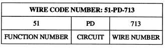
The ship’s wire marking codes are system oriented.
They consist of an alphanumeric code that identifies the
signal being carried by function number, circuit
designation, and assigned wire number. A typical
ship’s wire code number is shown in table 13-4.
Table 13-4.—A Typical Ship’s Wire Code Number
There are eight types of PANEL ASSEMBLY
connectors used in the switchboard. These connectors
are used for the linear movement switch assemblies,
fuse tester assembly, relay tester assembly, and power
distribution assembly. They consist of various types of
120-,
117-,
104-,
85-, 38-, 20-, 10-, and 3-pin
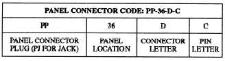
connectors. For wiring and maintenance purposes, a
common alphanumeric designation system is used to
identify specific circuit connections, as shown in table
13-5.
Table 13-5.—Panel Connection Cable Code
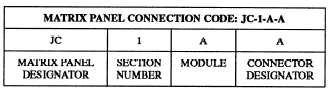
Within the switchboard are what are known as
matrix panels. The matrix panels interconnect the signal
paths between the ship’s wiring and the assembly
panels. The designation codes for matrix panel
connections are shown in table 13-6.
Table 13-6.—Matrix Panel Connection Code
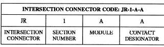
Intersection connectors are used to tie switchboard
sections together. Intersection connector codes are
identified in table 13-7.
Table 13-7.—Intersection Connector Code
The CSCP uses two types of connectors, a 10-pin
connector and an 85-pin connector. The l0-pin
connectors are designated JA, JB, JN, and JP. The
85-pin connectors are designated JC through JG, JH,
and JK. The alphanumeric identification shown in table
13-8 is used for CSCP connectors.
13-34