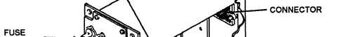
Figure 13-25.—Relay tester assembly.
Relay Tester Assembly
The relay tester assembly (figure 13-25) provides
the facilities for testing each type of relay used in the
DFCS and the CSCPs. Relay sockets are provided for
8-, 10-, and 16-pin relays. The rotary switch is used to
select the appropriate relay coil voltage. The toggle
switch is used to energize/deenergize the relay coil. The
indicator lamps indicate the state of the relay under test
(ENERGIZED/DEENERGIZED).
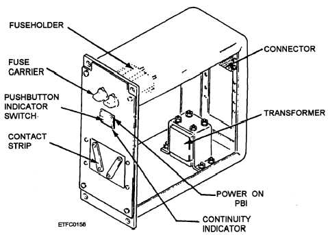
Fuse Tester Assembly
The fuse tester assembly (figure 13-26) is used to
test fuses for continuity. The POWER ON PBI is used
to apply power to the fuse tester. The POWER ON
indicator will light when the tester is on. When a good
fuse is placed across the contact strips, the
CONTINUITY INDICATOR light will come on. A
blown fuse placed across the contact strips will not light
the indicator, since there is no current path through the
fuse.
Figure 13-26.—Fuse tester assembly (DFCS).
13-32