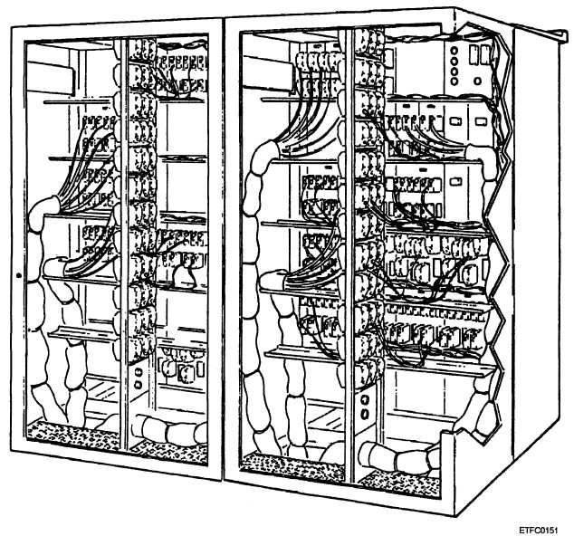
allow access to the interior of the switchboard. The
interior of the switchboard (figure 13-19) contains a
system of modules and terminal board connectors that
allow ship’s wiring to be interconnected to the
appropriate switch panels.
The switchboard panel locations are numbered for
identification purposes starting at the upper left corner
of the switchboard. The numbering continues from top
to bottom, left to right. Each panel is marked with a
designation plate mounted on the upper-left corner of
the panel assembly or with a blank plate.
Power Distribution Panel
The power distribution panel (figure 13-20)
provides a visual indication of power supplied to the
switchboard. Six indicators are mounted on the front
of the panel and lighted when the appropriate power has
been applied to the panel and distributed to the
remainder of the switchboard.
Linear Movement Switch
Assemblies
The majority of panel assemblies are linear
movement switch assemblies. These assemblies route
a specific number of circuits. The linear movement
switch assemblies are normally positioned by control
signals from the CSCP, but they may be manually
positioned.
There are two types of linear movement switch as-
semblies, the R3DLSO-lB/R5DLSO-lB (figure 13-21)
Figure 13-19.—DFCS interior.
13-28