The SECTOR REGISTER consists of three
pushbutton/indicators. The register displays the sector
number of the 60-degree sector in which the rotor is
located. The pushbuttons may be used to simulate a
sector angle. The eight pushbutton/indicators of the
RATIO REGISTER indicate or simulate the binary ratio
angle.
The +REF/OFF/-REF toggle switch allows
selection of positive (+REF) or negative (-REF)
reference voltage. The switch is set to the OFF position
for normal operations. The OSCILLATOR
potentiometer is used to vary the frequency of the S/D
converter test circuits from 2 to 100 Hz. With the
HIGH/LOW toggle switch in the HIGH position, the
S/l) converter is enabled for continuous recycling when
in the test mode. When the switch is in the LOW
position, the recycling rate can be varied from 2 to 100
conversions a second using the OSCILLATOR
potentiometer.
The OUTPUT REGISTER has 15 pushbutton/
indicators and a clear pushbutton. The register
indicates the 15-bit BAM output of the S/D converter.
Each bit-position indicator equates to a degree value
portion of the summed synchro-mechanical angle.
TOPIC 3—SWITCHBOARDS
Shipboard tactical data system devices are
interconnected with each other and with equipments
in other shipboard subsystems through switch-
boards. Combat systems use two major types of
switchboards: digital switchboards and analog
switchboards.
Digital switchboards primarily interconnect digital
devices. These types of interfaces include computer-to-
computer interfaces and computer-to-peripheral
devices and other serial or parallel digital inter-
faces.
Analog switchboards provide the interconnection
for analog devices and signals including control and
status signals, synchro signals, and linear signals. In
addition, analog switchboards provide supply and
return voltages and reference voltages for analog signal
exchanges. Most current shipboard combat direction
systems use a combination of analog and digital
switchboards to completely interface CDS equipments
with each other and with other shipboard sub-
systems.
DIGITAL SWITCHBOARDS
The two basic types of shipboard digital
switchboards are manual switchboards and remotely
Figure 13-15.—Sample manual switching configuration.
controlled switchboards.
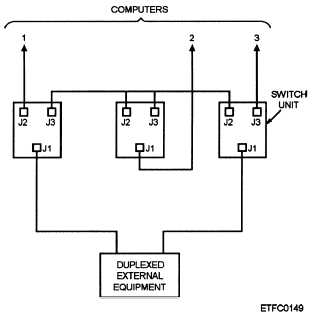
Manual switchboards are made up of variable
configurations of three-position or five-position
switches (figure 13-14). Each switch must be manually
positioned for the interconnection required by the
current system configuration. At least two manual
switches, one for input and one for output, are required
for each I/O device or computer channel to allow for the
complete range of system configuration requirements
(figure 13-15). Manual switchboards are for the most
part being replaced by remotely controlled
switchboards.
13-25