FLOW-MONITORING DEVICES
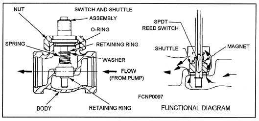
low-flow switch is normally found in the secondary
cooling system to monitor the overall coolant flow. It
Most systems incorporate one or more types of
is electrically connected to a common alarm circuit to
devices to monitor the flow of distilled water through
warn personnel when the system flow rate drops
the system to ensure that the electronic equipment is
below a specified minimum value. A typical cooling
supplied with an adequate flow of distilled water. A
system low-flow switch is shown in figure 2-15.
Figure 2-15.—Cooling system low-flow switch.
The main operating parts of the cooling system
low-flow switch consist of a hermetically sealed reed
switch and a permanent magnet attached to an internal
shuttle. With the proper flow of coolant, the shuttle
moves the magnet up and away from the reed switch,
which keeps the reed switch contacts open. When the
coolant flow drops below the minimum for a flow
switch, the shuttle is forced down by the spring to a
balanced condition against the flow of the distilled
water. The magnetic field is now close enough to
cause the reed switch to close and to activate the low-
flow alarm.
A small flow switch is used in electronic equip-
ment to monitor the flow to individual components.
The flow of water through the orifice causes a pres-
sure drop across it. This pressure drop causes the
diaphragm to move against the spring. When the dif-
ferential pressure (pressure drop) is sufficient, the
microswitch activates to indicate that the switch has
the proper flow through it. You should be sure that the
flow switch is defective before overhauling or replac-
ing it, as the problem could be a partially closed
supply/return valve, an obstruction in the coolant line,
an insufficient coolant pressure, or many other things.
By using the coolant system pressure gages and/or the
installation of a permanent or a temporary in-line
flowmeter, you should be able to correctly isolate the
problem.
In the secondary cooling system, a full-flow sys-
tem flowmeter is provided to enable you to monitor
the total system flow rate for troubleshooting pur-
poses. Three types of system flowmeters are installed
aboard ships; all of which monitor the coolant-flow
rate. They are the venturi flowmeter, the orifice flow-
meter, and the rotameter. Most systems incorporate
one secondary coolant flowmeter and one or more
smaller flowmeters to ensure that the electronic equip-
ment is being supplied with an adequate flow of cool-
ant.
A typical equipment-flow switch is shown in
figure 2-16.
2-17


