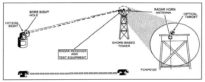
The optical LOS or boresight axis is the fixed
On radars where the foresight axis is not fixed, the
reference for some radars, while for others, it is not.
telescope is moveable and is adjusted parallel to the
On radars where the boresight axis is the fixed refer-
reference RF beam. Figure 4-1 shows a radar colli-
ence, the RF beams are aligned to the boresight axis.
mation configuration with a shore-based tower setup.
Figure 4-1.—Radar collimation with a shore-based tower setup.
TARTAR GMFCS RADAR
COLLIMATION REQUIREMENTS
Because different types of radar are used in the
missile and gun systems, the collimation requirements
for each radar are different. This section briefly dis-
cusses the requirements for the Tartar GMFCS.
The primary radar for the Tartar GMFCS is the
Radar Set AN/SPG-51C/D. It is an automatic target-
acquisition and missile-guidance radar set that uses
C-band, pulsed-Doppler techniques for target tracking
and an X-band continuous-wave (CW) illuminator to
4-2
provide guidance for the semiactive homing Tartar
missile.
As shown in figure 4-2, the C-band and X-band
feed horns on the radar antenna are effectively located
at the same feed point so that the track and CW illu-
minator RF beams are parallel, within specified toler-
ance. A wide continuous-wave illuminator (CWI)
reference beam is also generated by the X-band horn,
which is located in the center of the antenna reflector
to fill in any nulls in the CWI main beam and to
provide missile rear reference information. The beam
relationships are shown in figure 4-3.


