Monitor Deflection Function.— The monitor
deflection function of the DCC receives the vertical
and horizontal sync signals from the monitor interface
sync processor. These signals are used to develop the
voltages necessary to drive the vertical and horizontal
deflection coils on the CRT yoke. The monitor
deflection function also produces dynamic focus
voltages to control the focus of the CRT beam.
Video Amplifier Function.— The video amplifier
function receives the selected video signal and
develops the voltages necessary to drive the CRT
cathode and control grid (grid 1).
GRAPHICS
TERMINAL
SHELF.— The
graphics terminal shelf is located in the bullnose of
the DCC and contains the trackball assembly and the
data entry keyboard.
The trackball and keyboard
functions are
controlled by
the bullnose
microprocessor and interface with the system
computer through the C-DITEG. The bullnose
microprocessor monitors the switches (trackball and
keyboard) for any operator action, develops a serial
I-data word, and sends it to the C-DITEG. The
microprocessor program also receives O-data from the
C-DITEG and processes it. The O-data contains
commands to light various keys on the entry
keyboard.
CONTROL PANEL MODULE.— The control
panel module is located on the left side of the graphics
monitor. Depending on the configuration and system,
the control panel module can contain a variety of
switch panels. There can be one or two CCAEPs, a
6 x 7 category select panel, and a communications
station.
The control panel module also contains a
microprocessor that controls the communication with
the C-DITEG. The microprocessor program monitors
the switches in the various panels for activity, stores
any action, creates an I-data word, and transmits the
I-data to the computer via the C-DITEG.
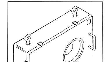
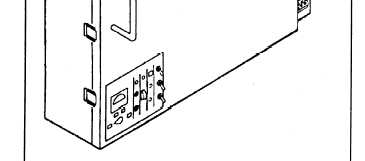
Figure 4-21.—The Projection Plotting Unit
PT-525/UYQ-21(V).
PROJECTION PLOTTING UNIT
PT-525/UYQ-21 (LARGE SCREEN DISPLAY)
Large
screen
display capability for the
AN/UYQ-21(V) system is provided by the projection
plotting unit (PPU), either the PT-525/UYQ-21(V) or
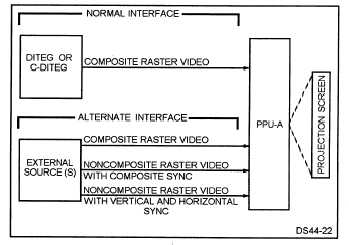
Figure 4-22.–The PPU interface options.
4-19


