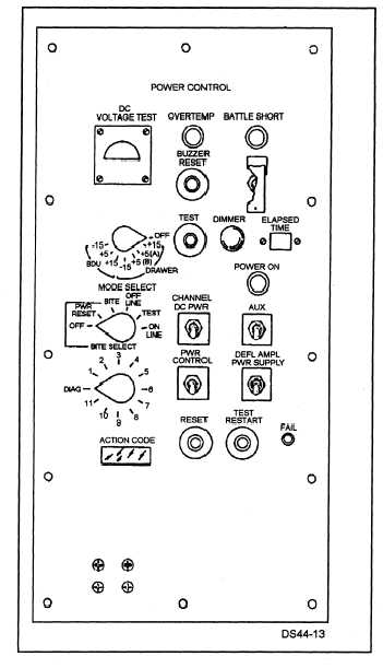
Figure 4-13.—A conso1e electronics drawer
power control panel.
into Manchester encoded serial data before
transferring it to the CDB. If the data is in parallel
format, the parallel data drivers provide the proper
level shifting and gating to the system computer.
DIAGNOSTIC FUNCTION.— The diagnostic
function controls the running of the various built-in
self tests.
There are three levels of diagnostic
testing. Level I tests are run automatically when the
power is turned on.
Level I tests are basic checks
of the system clocks, memory timing, and operation
of the four processors.
If no errors are detected
during level I tests, the level II tests are run. Level
II tests are more detailed and check the system
RAM, processor support subfunctions, refresh
memory, display memory, and processor interfaces.
Level III tests are detailed interactive tests. Level
III tests are controlled by the technician and can be
run when the power control panel MODE SELECT
switch is in the BITE (built-in test equipment)
position.
Figure 4-13 shows a typical console
electronics drawer power and control panel. There
are several different power and control panels, but
all have similar controls and indicators. If a fault is
detected during level I or II testing, the FAIL
indicator on the CED power control panel will light.
Internal fault indicators, located on the circuit cards,
may also be lighted if a level I or II test fails. A
numerical code may be displayed in the ACTION
CODE readout on the CED power panel for level I,
II, or III test failures. For exact operating procedures
and fault isolation codes, you should refer to the
Maintenance Instruction Manual for Computer
Display Set AN/UYQ-21(V), Volume 2, SE685-AF-
MMM-020/UYQ-21(V).
POWER DISTRIBUTION.— The power
distribution function converts the ac input power
into +5, +15, and -15vdc for use in the console.
The power distribution function also monitors the
operating
temperature
a n d p r o v i d e s a n
over-temperature alarm when the console operating
temperature reaches 150°F.
If the console
temperature reaches 170°F, an unsafe condition is
present and the console will automatically shut
down. The automatic shutdown can be overridden
by the BATTLE SHORT switch.
Basic Display Unit
The basic display unit (BDU) is used to display
sensor data and computer-controlled symbology.
Data input to the computer is accomplished by
variable function keys around the CRT. Figure 4-14
illustrates the BDU. The BDU consists of an 11" x
13" vector scan CRT and seven functional areas to
support the display, as shown in the block diagram
(figure 4-15). The functional areas of the BDU are:
Input/output function
4-12


