Figure 3-17.—A PPI tactical
symbology display.
CRT CONTROL PANEL.— The CRT control
panel contains the CRT, optional plotting board, and
some of the controls for the console. The CRT
displays tactical symbology as shown in figure 3-17.
The CRT display of sensor data and symbology is
controlled from the display control panel.
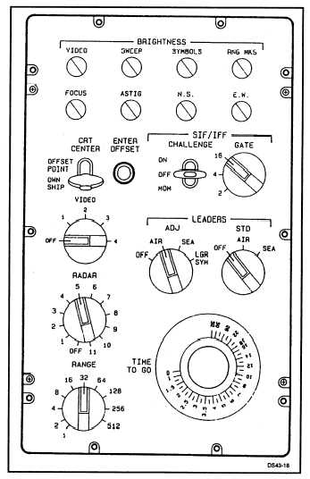
DISPLAY CONTROL PANEL.— The display
control panel is located to the right of the CRT and
contains the switches and controls to regulate the CRT
display as shown in figure 3-18. The BRIGHTNESS
section of the panel contains a potentiometer to
control the display of video, sweep, symbols, and
range marks.
It also contains the potentiometer to
control the CRT focus, astigmatism, and the centering
adjustments.
Additionally, the display control panel contains
the switches to select the radar, range of the radius of
the CRT, select offset, and control symbol leaders.
DATA ENTRY PANELS.— For data entry
purposes, the console is equipped with a computer-
controlled action entry panel (CCAEP), and may be
equipped with either a 6 by 7 panel or category select
switch panel, a digital data entry unit, or an optional
alphanumeric keyboard and a trackball unit. Figure 3-
19 shows a console with the 6 by 7 panel and the
alphanumeric keyboard. The trackball is recessed in
the trackball well along with the ball tab enable, ball
tab center, hook, and sequence pushbuttons.
Computer-Controlled Action Entry Panel
(CCAEP).— The computer-controlled action entry
panel (CCAEP) provides greater flexibility than its
predecessor, the mode roller. CCAEPS consist of 24
switches arranged in 4 rows of 6 as shown in figure
3-20. The bottom row of six switches has fixed labels
and functions.
Each of the remaining 18 switch
positions has 48 possible labels, or functions,
independently controlled by computer output data and
an auxiliary LED indicator.
The computer program controls the selection of a
Figure 3-18.—A PPI display control panel.
3-14


