the sweep counters in the display console at the same
rate.
The output of the sweep counters is
continuously fed to the deflection circuitry, and the
beam will be deflected at 45 degrees.
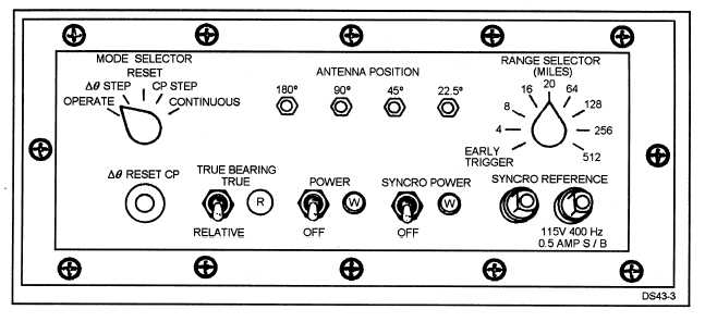
Figure 3-3 shows the front panel of a typical RAC.
The RACs installed on your ship may not look exactly
like this one. On this particular RAC panel, internal
testing is accomplished by using the MODE
SELECTOR switch. Most RACs have a similar
MODE SELECTOR switch that operates in the same
basic manner. When the MODE SELECTOR switch
is in the OPERATE position, the RAC operates with
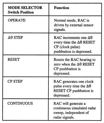
its radar. The other switch positions of the front panel
are used for maintenance and troubleshooting as
shown in table 3-1.
The RACs are combined together into a cabinet or
cabinets called the radar azimuth converter group.
The cabinets provide a common power supply and
mountings for several RACs. The output of the RACs
are fed to the radar data distribution switchboards
(RDDSs).
RADAR DATA DISTRIBUTION
Table 3-1.—The MODE SELECTOR
Switch Functions
SWITCHBOARD (RDDS)
signals (video levels) directly from each sensor.
The radar data distribution switchboard (RDDS)
The RDDS provides the display consoles access to
routes radar and sonar antenna position data and
all the sensors connected to the switchboard. The
timing signals from the sensor RACs to the display
RDDS can accept inputs from 11 radar or sonar
consoles. It also receives up to four separate video
sensors and provide outputs to display consoles on 10
output channels, one standard display console per
Figure 3-3.—A typical RAC front panel.
3-4


