The LMS-11 is capable of measuring and
displaying link signal data for the network as a whole,
as well as for individual units. It can be used for
periodic equipment checks or for continuous
monitoring to determine the condition of all members
of the net.
LMS-11 SYSTEM CONFIGURATION
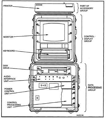
The LMS-11 consists of three groups of
equipment:
a data processing group (DPG), a
control/display group (CDG), and an accessory group
(AG). The LMS-11 is shown in figure 3-3.
The LMS-11 is designed to be portable, and the
equipment is installed in three carrying cases. The
equipment cases that house the electronic units of the
DPG and CDG provide isolation from shock and
vibration. The CDG is designed to be mounted on the
top of the DPG cases. Four latches fasten the two
units together and provide a desk height, self-
contained workstation. The system printer, which is
part of the accessory group, is mounted on the top of
the CDG equipment case. When the LMS-11 is
installed, the accessory group case provides storage
for the DPG and CDG equipment case covers. The
LMS-11 is normally located near the data terminal
set, but it may be installed anywhere near a 600-ohm
Link-11 audio signal.
Data Processing Group
The equipment required for the LMS-11 to
receive, sample, and process Link-11 audio signals is
contained in the data processing group. The DPG also
provides power control and distribution to the CDG
and accessories. The DPG consists of the following
equipment:
The control processing unit
The audio interface unit
The dual 3.5-inch floppy disk drive unit
The power control unit
Figure 3-3.—The LMS-11.
CONTROL PROCESSING UNIT.— The
control processing unit consists of the HP9920U
computer with an additional 2 MB of ram and
associated circuit card assemblies (CCA). These
circuit cards include the following:
Color output CCA
Composite Video CCA
Data communications interface
HP interface bus (HP-IB)
Analog-to-digital converter assembly
Fast Fourier Transform (FFT) processor
The color output CCA and the composite video CCA
provide the necessary signals to drive the color
monitor. The data communications interface provides
an RS-232C asynchronous serial interface for the
color printer.
The HPIB is used to interface the
system keyboard and the dual disk drives to the
computer.
3-7


