Dehydrator
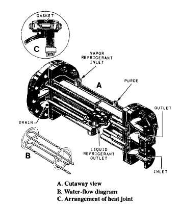
Figure 10-7.-Water-cooled condenser for an R-12 refrigera-
tion system.
ACCESSORIES
In addition to the five main components of a
refrigeration system, a number of controls and
accessories are required. The most important of these
are described briefly in the following paragraphs.
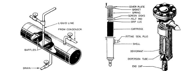
Figure 10-8.-Receiver.
A dehydrator, or dryer, containing silica gel or
activated alumina, is placed in the liquid refrigerant line
between the receiver and the TXV. In older installations,
bypass valves allow the dehydrator to be cut in or out of
the system. In newer installations, the dehydrator is
installed in the liquid refrigerant line without any bypass
arrangement. A dehydrator is shown in figure 10-9.
Moisture Indicator
A moisture indicator is located either in the liquid
refrigerant line or built into the dehydrator. The moisture
indicator contains a chemically treated element that
changes color when there is an increase of moisture in
the refrigerant. The color change is reversible and
changes back to a DRY reading when the moisture is
removed from the refrigerant. Excessive moisture or
water will damage the moisture indicator element and
turn it gray, which indicates it must be replaced.
Solenoid Valve and Thermostatic Control
Switch
A solenoid valve is installed in the liquid line
leading to each evaporator. Figure 10-10 shows a
solenoid valve and the thermostatic control switch that
operates it. The thermostatic control switch is connected
by long flexible tubing to a thermal control bulb located
in the refrigerated space. When the temperature in the
refrigerated space drops to the desired point, the thermal
control bulb causes the thermostatic control switch to
Figure 10-9.-Refrigeration dehydrator.
10-9


