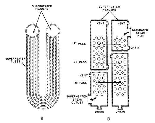
Figure 4-7.—Diagram of a superheater.
one type of boiler to another and from one boiler
manufacturer to another. Figure 4-6 shows the
arrangement of the steam drum internal fittings
in a single-furnace boiler.
. The feedwater pipe receives feedwater
from the economizer and distributes it throughout
the length of the steam drum.
. The chemical feed pipe is used to inject
chemicals into the boiler to maintain the proper
pH and phosphate balance in the boiler water.
l The surface blow pipe is used to remove
suspended solid matter that floats on top of the
water and to lower the steam drum water level,
when necessary. The surface blow pipe is also used
to blow water out to lower the chemical level in
the boiler when it becomes too high.
. The dry pipe is used to direct the steam to
the steam drum outlet nozzle after it leaves the
scrubbers.
. The vortex eliminators are used to reduce
the swirling motion of the water as it enters the
downcomers.
l The baffle plates are used to direct the
steam to the steam separators.
l The cyclone steam separators remove
moisture from the steam. This is accomplished by
the steam spinning or changing direction. The
water drains back into the steam drum while the
steam continues upward through a screen and
scrubber that removes still more moisture.
After the steam leaves the scrubbers, it goes
to the dry pipe (fig. 4-6). From there it leaves the
steam drum through the steam drum outlet.
Figure 4-7, view A, shows the steam going to the
inlet header of the superheater and passing
through the U-shaped tubes of the superheater to
the next header (fig. 4-7, view B). This header is
called the first pass or intermediate header. Steam
may pass through the U-shaped tubes several
times before passing to the outlet header. Each
time the steam goes from one header to the next
header it is called a pass. The number of passes
the steam makes in a superheater varies with
different boilers and the degree of superheat that
is required for a particular ship.
4-9


