If an RTD is faulty, you should replace it. Internal
repairs cannot be made at the shipboard level. Until you
can replace the faulty RTD, inform the watch standers
that the RTD is unreliable. THe engine-room watch
standers should take local readings periodically to make
sure the equipment is operating normally.
Resistance Temperature Elements
The RTEs are the most common type of temperature
sensor found in gas turbine propulsion plants. The RTEs
operate on the same principle as the RTDs. As the
temperature of the sensor increases, the resistance of the
RTE increases proportionally. All RTEs that you
encounter have a platinum element. They have an
electrical resistance of 100 ohms at a temperature of
32°F. Four different temperature ranges of RTEs are
commonly used, and you will find that the probe sizes
vary. The four temperature ranges and their
corresponding probe sizes are as follows:
TEMPERATURE RANGE
RTE PROBE LENGTH
(Degree Fahrenheit)
(Inches)
-20 to +150
6
0 to +400
2, 4, and 10
0 to +1,000
2
-60 to +500
6
You may find some RTEs connected to remote
mounted signal conditioning modules. These modules
convert the ohmic value of the RTE to an output range
of 4 to 20 mA dc. However, most RTEs read their value
directly into the propulsion electronics as an ohmic
value.
The RTEs with temperature ranges from 0°F to
+400°F and from -60° to +500°F are commonly
mounted in thermowells. Since you can change an RTE
without securing the equipment it serves, maintenance
is simplified.
ELECTRICAL INDICATING
INSTRUMENTS
Electrical indicating instruments (meters) are used
to display information that is measured by some type of
electrical sensor. Although meters display units such as
pressure or temperature, the meters on the control
console are, in fact, dc voltmeters. The signal being
sensed is conditioned by a signal conditioner. This is
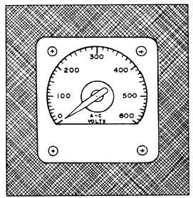
Figure 11-16.—An ac voltmeter.
then converted to 0 to 10 volts dc, which is proportional
to the parameters being sensed.
Electrical values, such as power and current, are
measured and displayed at ship’s service switchboards.
Normally, shipboard repair is not done on switchboard
meters. If you suspect the switchboard meters are out of
calibration or broken, you should have them sent to a
repair facility. You can find more information on the
theory of operation of these meters in the Navy
Electricity and Electronics Training Series (NEETS),
Module 3, Introduction to Circuit Protection, Control,
and Measurement, NAVEDTRA 172-03-00-79.
VOLTMETERS
Both dc and ac voltmeters determine voltage the
same way. They both measure the current that the
voltage is able to force through a high resistance. This
resistance is connected in series with the indicating
mechanism or element. Voltmeters installed in
switchboards and control consoles (fig. 11-16) all have
a fixed resistance value. Portable voltmeters, used as test
equipment, usually have a variable resistance.
For both installed and portable voltmeters,
resistances are calibrated to the different ranges that the
meters will display. The normal range for the
switchboard and electric plant meters is 0 to 600 volts.
11-9


