the failing unit. There is one case, however, where this
is not true. During an overspeed condition, both units
increase in frequency, but the failing unit is the one with
the higher load.
SYNCHROSCOPES
Before connecting a three-phase generator to bus
bars already connected to one or more generators, you
must make sure that certain conditions prevail. A
synchroscope is the device you use to find out if the
following required conditions have been met:
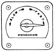
Figure 11-20.—Synchroscope.
1.
2.
3.
4.
5.
Phase sequence for the both generator and bus
bars must be the same.
The generator and the bus-bar voltages must be
the same.
The generator and bus-bar frequency must be the
same.
The generator frequency must be practically
constant for an appreciable period of time.
The generator and bus-bar voltages must be in
phase. They must reach their maximum voltages
at the same time; therefore, when connected,
they will oppose excessive circulation of current
between the two machines.
Figure 11-20 shows a synchroscope. It is basically
a power factor meter connection to measure the phase
relationship between the generator and bus-bar voltages.
The moving element is free to rotate continuously. When
the two frequencies are exactly the same, the moving
element holds a fixed position. This shows the constant
phase relationship between the generator and bus-bar
voltages. When the frequency is slightly different, the
phase relationship is always changing. When this
happens, the moving element of the synchroscope
rotates constantly. The speed of rotation is equal to the
difference infrequency; the direction shows whether the
generator is fast or slow. The generator is placed on line
when the pointer slowly approaches a mark. This mark
shows that the generator and bus-bar voltages are in
phase.
PHASE-SEQUENCE INDICATORS
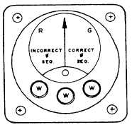
A phase-sequence indicator (fig. 11-21) is used to
determine the sequence in which the currents of a
three-phase system reach their maximum values.
Ships have phase-sequence indicators installed in
switchboards that may be connected to shore power.
These instruments indicate whether shore power is in
the correct phase sequence with the ship before
shipboard equipment is connected to shore power.
Three-phase motors, when connected to incorrect
phase-sequence power, rotate in the opposite direction.
The phase-sequence indicator has three neon lamps
that light when all three phases are energized. A meter
connected to a network of resistors and condensers
shows correct or incorrect sequence on a marked scale.
LIQUID-LEVEL INDICATORS
As a watch stander, you monitor systems and tanks
for liquid levels. Sometimes, you are only required to
know if a level exceeds or falls below a certain preset
parameter. At other times, you need to know the exact
level. If only a predetermined limit is needed, you can
use a float switch. When the set point is reached the float
switch will make contact and sound an alarm. If you
need to know a specific level, you must use a variable
sensing device. The sensor used to indicate a tank level
is commonly called a tank level indicator (TLI). This
sensor tells you the exact amount of liquid in a tank. In
the following paragraphs, we will describe the operation
Figure 11-21.—A phase-sequence indicator.
11-11


