compressed, followed by a cooling and moisture
removal process similar to the first stage.
High-Pressure Air Compressors
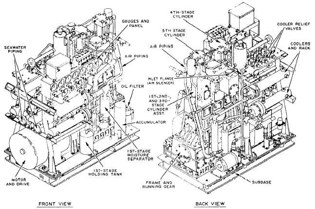
The HPAC is a vertical, five-stage, reciprocating air
compressor. It is driven by being directly connected to
an electrical motor. Refer to figures 10-27 and 10-28 as
we describe the compressor.
The subbase supports the compressor assembly, the
electric drive motor, and the coolers and rack assembly.
The crankcase is bolted directly to the subbase and is
made up of the frame and frame extension. The frame
houses the crankshaft and oil pump. The frame
extension is open to the atmosphere and isolates the
conventionally lubricated frame from the oil-free
cylinders. The crosshead guides are machined in the
frame extension. A uniblock casting contains the first
three-stage cylinders and is mounted on the frame
extension (fig. 10-28). The cylinders are arranged in
line. The first stage is in the center, the second stage is
at the motor end, and the third stage is outboard. The
fourth stage is mounted above the second stage, and the
fifth stage is above the third stage. The fourth- and
fifth-stage pistons are tandem mounted to the second-
and third-stage pistons, respectively.
During operation, ambient air is drawn into the
first-stage cylinder through the inlet falter and inlet
valves. The first stage is double acting, and air is drawn
into the lower cylinder area as the piston is moving
upward. At the same time, air in the upper cylinder is
being compressed and forced out the upper discharge
valve. As the piston moves downward, air is drawn into
the upper cylinder; likewise, air in the lower cylinder is
being compressed and forced out the lower discharge
valve. Compressed air leaves the first-stage discharge
valves and flows through the first-stage intercooler, and
into the first-stage moisture separator.
The first-stage separator has a small tank mounted
on the side of the compressor frame below the gauge
panel and a holding tank mounted below the cooler rack.
The separators for the remaining stages handle smaller
volumes of air due to compression; as a result, the
separators and holding chambers are smaller and are
integrated into one tank. Condensate is removed from
the air as it collides with the internal tank baffles and
collects in the holding chamber.
Figure 10-27.—HPAC.
10-29


