and vaporizes, it picks up latent heat of vaporization
from the space being cooled. The refrigerant
continues to absorb latent heat of vaporization until
all the liquid has been vaporized. By the time the
refrigerant leaves the cooling coil, it has not only
absorbed this latent heat of vaporization. It has also
picked up some additional heat; that is, the vapor
has become superheated. As a rule, the amount of
superheat is 4° to 12°F.
The refrigerant leaves the evaporator as low-
pressure superheated vapor. The remainder of the
cycle is used to dispose of this heat and convert the
refrigerant back into a liquid state so that it can
again vaporize in the evaporator and absorb the heat
again.
The low-pressure superheated vapor is drawn out
of the evaporator by the compressor, which also
keeps the refrigerant circulating through the system.
In the compressor cylinders, the refrigerant is
compressed from a low-pressure, low-temperature
vapor to a high-pressure vapor, and its temperature
rises accordingly.
The high-pressure R-12 vapor is discharged from
the compressor into the condenser. Here the
refrigerant condenses, giving up its superheat
(sensible heat) and its latent heat of condensation.
The condenser may be air or watercooled. The
refrigerant, still at high pressure, is now a liquid
again. From the condenser, the refrigerant flows into
a receiver, which serves as a storage place for the
liquid refrigerant in the system. From the receiver,
the refrigerant goes to the TXV and the cycle begins
again.
This type of refrigeration system has two
pressure sides. The LOW-PRESSURE SIDE extends
from the TXV up to and including the intake side of
the compressor cylinders. The HIGH-PRESSURE
SIDE extends from the discharge valve of the
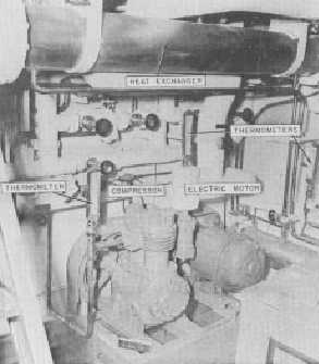
compressor to the TXV. Figure 10-2 shows most of
the components on the high-pressure side of an R- 12
system as it is installed aboard ship.
MAIN PARTS OF THE R-12 SYSTEM
The main parts of an R- 12 refrigeration system
are shown diagrammatically in figure 10-3. The
six primary components of the system include
the
1. TXV,
2. evaporator,
3. capacity control system,
4. compressor,
5. condenser, and
6. receiver.
47.92
Figure 10-2.-High-pressure side of an R-12
installation aboard ship.
Additional equipment required to complete the
plant
includes
piping,
pressure
gauges,
thermometers, various types of control switches and
control valves, strainer, relief valves, sight-flow
indicators, dehydrators, and charging connections.
In this chapter, we will deal with the R-12 system
as though it had only one evaporator, one
compressor, and one condenser. As you can see from
figure 10-3, however, a refrigeration system usually
has more than one evaporator, and it may include an
additional compressor and condenser units.
Thermostatic Expansion Valve (TXV)
Earlier, you learned that the TXV regulates the
amount of refrigerant to the cooling coil. The amount
of refrigerant needed in the coil depends, of course,
on the temperature of the space being cooled.
The thermal control bulb, which controls
the opening and closing of the TXV, is clamped
to the cooling coil near the outlet. The substance
in the thermal bulb varies, depending on the
refrigerant used. The expansion and contraction
(because of temperature change) transmit a
pressure to the diaphragm. This causes the
diaphragm to be moved downward, opening
10-3


